
Datasheet


Section 23 Power-Down Modes
R01UH0310EJ0500 Rev. 5.00 Page 1157 of 1384
Sep 25, 2012
H8S/2426, H8S/2426R, H8S/2424 Group
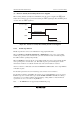
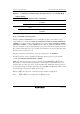
(4) Hardware Standby Mode Timing when Power Is Supplied
When entering hardware standby mode immediately after the power is supplied, the RES signal
must be driven low for a given period with retaining the STBY signal high. After the RES signal is
canceled, drive the STBY signal low.
(1) Power supply
RES
(2) Reset period
(3) Hardware standby mode
STBY
Figure 23.4 Hardware Standby Mode Timing when Power Is Supplied
23.2.5 Module Stop Function
Module stop function can be set for individual on-chip peripheral modules.
When an MSTP bit in MSTPCR, EXMSTPCR, or RMMSTPCR is set to 1, the corresponding
module stops operation at the end of the bus cycle and a transition is made to module stop state.
The CPU continues operating independently.
When an MSTP bit is cleared to 0, the corresponding module stop state is cleared and the module
starts operating at the end of the bus cycle. In module stop state, part of SCI registers and the
internal state of SSU are reset but the internal states of the other modules are retained.
After reset clearance, all modules other than the EXDMAC*, DMAC, DTC, and on-chip RAM are
in module stop state.
The module registers that are set in module stop state cannot be read or written to.
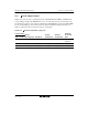
The module-stop function for RAM is only effective for on-chip RAM. When an area of on-chip
RAM is set up as an external address space by bits RAME and EXPE in SYSCR, the resulting
external space is accessible regardless of the module-stop setting. Table 23.3 lists the kinds of
operation in case of access to the on-chip RAM area.
Note: * The EXDMAC is not supported by the H8S/2424 group.