
Datasheet
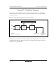


Section 22 Clock Pulse Generator
Page 1132 of 1384 R01UH0310EJ0500 Rev. 5.00
Sep 25, 2012
H8S/2426, H8S/2426R, H8S/2424 Group
22.1 Register Descriptions
The clock pulse generator has the following registers.
• System clock control register (SCKCR)
• PLL control register (PLLCR)
22.1.1 System Clock Control Register (SCKCR)
SCKCR controls
φ clock output and selects operation when the PLLCR register setting is changed.
Bit Bit Name Initial Value R/W Description
7 PSTOP 0 R/W φ Clock Output Disable
Controls
φ output.
Normal Operation
0: φ output
1: Fixed high
Sleep Mode
0:
φ output
1: Fixed high
Software Standby Mode
0: Fixed high
1: Fixed high
Hardware Standby Mode
0: High impedance
1: High impedance
All module clock stop mode
0:
φ output
1: Fixed high
6 ⎯ 0 R/W Reserved
This bit can be read from or written to. However,
the write value should always be 0.