
Technical information

13
SINGLE-CHIP 8-BIT CMOS MICROCOMPUTER
MITSUBISHI MICROCOMPUTERS
38C8 Group
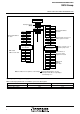
I/O PORTS
[Direction Registers]
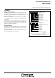
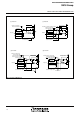
The I/O ports P0–P3 and P41–P47 have direction registers which
determine the input/output direction of each individual pin. Each bit
in a direction register corresponds to one pin, each pin can be set to
be input port or output port.
When “0” is written to the bit corresponding to a pin, that pin be-
comes an input pin. When “1” is written to that bit, that pin becomes
an output pin.
If data is read from a pin set to output, the value of the port output
latch is read, not the value of the pin itself. Pins set to input are float-
ing. If a pin set to input is written to, only the port output latch is
written to and the pin remains floating.
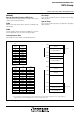
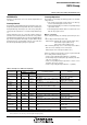
Pull-up Control
By setting the PULL register A (address 001616) or the PULL register
B (address 001716), ports P0 to P4 except for port P40 can control
pull-up with a program.
However, the contents of PULL register A and PULL register B do not
affect ports programmed as the output ports.
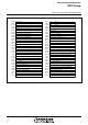
Fig. 10 Structure of PULL register A and PULL register B
P00–P03 pull-up
P04–P07 pull-up
P1
0–P13 pull-up
P14–P17 pull-up
P2
0–P23 pull-up
P24–P27 pull-up
P3
0–P33 pull-up
Not used (return “0” when read)
PULL register A
(PULLA: address 0016
16)
0
:
N
o
p
u
l
l
-
u
p
1
:
P
u
l
l
-
u
p
b7 b
0
N
o
t
e
:
T
h
e
c
o
n
t
e
n
t
s
o
f
P
U
L
L
r
e
g
i
s
t
e
r
A
a
n
d
P
U
L
L
r
e
g
i
s
t
e
r
B
d
o
n
o
t
a
f
f
e
c
t
p
o
r
t
s
p
r
o
g
r
a
m
m
e
d
a
s
t
h
e
o
u
t
p
u
t
p
o
r
t
.
Not used (return “0” when read)
P41 pull-up
P4
2 pull-up
P4
3 pull-up
P44 pull-up
P45 pull-up
P4
6 pull-up
P4
7 pull-up
b
7b
0
PULL register B
(PULLB: address 0017
16)