REJ10J0037-0100(T) M301N2T-PRB User’s Manual Pod probe for M16C/1N Group Rev.1.00 Mar.
Keep safety first in your circuit designs! 1. Renesas Technology Corp. puts the maximum effort into making semiconductor products better and more reliable, but there is always the possibility that trouble may occur with them. Trouble with semiconductors may lead to personal injury, fire or property damage.
M301N2T-PRB User’s Manual Preface Preface The M301N2T-PRB is a pod probe for the M16C/1N Group of Renesas 16-bit MCUs. The M301N2T-PRB is used by connecting to a PC4701 emulator main unit (excluding the PC4701L and PC4700L) and the M30100T3-RPD-E emulation pod main unit. This user's manual mainly describes specifications of the M301N2T-PRB pod probe and how to setup it.
M301N2T-PRB User’s Manual Important Important Before using this product, be sure to read this user’s manual carefully. Keep this user’s manual, and refer to this when you have questions about this product. Emulator: The emulator in this document refers to the following products that are manufactured by Renesas Technology Corp.
M301N2T-PRB User’s Manual Important Usage restrictions: This emulator has been developed as a means of supporting system development by users. Therefore, do not use it as a device used for equipment-embedded applications.
M301N2T-PRB User’s Manual Precautions for Safety Precautions for Safety Definitions of Signal Words In both the user’s manual and on the product itself, several icons are used to insure proper handling of this product and also to prevent injuries to you or other persons, or damage to your properties. This chapter describes the precautions which should be taken in order to use this product safely and properly. Be sure to read this chapter before using this product.
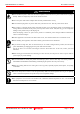
M301N2T-PRB User’s Manual Precautions for Safety 警告警告 WARNING Warnings for AC Power Supply: If the attached AC power cable does not fit the receptacle, do not alter the AC power cable and do not plug it forcibly. Failure to comply may cause electric shock and/or fire. Use an AC power cable which complies with the safety standard of the country. Do not touch the plug of the AC power cable when your hands are wet. This may cause electric shock. This product is connected signal ground with frame ground.
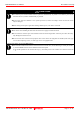
M301N2T-PRB User’s Manual Precautions for Safety CAUTION 注意注意 Cautions to Be Taken for Turning On the Power: Turn ON the power of the emulator and user system as simultaneously as possible. Turn OFF the power of the emulator and user system as simultaneously as possible. Do not leave either the emulator or user system powered on, because of leakage current the internal circuits may be damaged. When turning ON the power again after shutting OFF the power, wait about 10 seconds.
M301N2T-PRB User’s Manual Contents Contents Page Preface ................................................................................................................................................................. 3 Important .............................................................................................................................................................. 4 Precautions for Safety...............................................................................................
M301N2T-PRB User’s Manual Contents Page 4. Hardware Specifications ................................................................................................................................ 32 4.1 Target MCU Specifications ........................................................................................................................ 32 4.2 Differences between the Actual MCU and Emulator .................................................................................
M301N2T-PRB User’s Manual Terminology Terminology Some specific words used in this user's manual are defined as follows: Emulator system This means an emulator system built around the PC4701 emulator. The PC4701 emulator system is configured with an emulator main unit, emulation pod, pod probe, host machine and emulator debugger. Emulator main unit (Hereafter PC4701) This means a generic name for emulators for M16C, 7700, 740 Families.
M301N2T-PRB User’s Manual 1. Outline 1. Outline This chapter describes the package components, the system configuration, the specifications of the emulator functions and the operating environment. 1.1 Package Components The M301N2T-PRB package consists of the following items. When unpacking it, check to see if your M301N2T-PRB contains all of these items. Table 1.
M301N2T-PRB User’s Manual 1. Outline 1.3 System Configuration 1.3.1 System Configuration Figure 1.1 shows a configuration of the PC4701 system. Emulator debugger M3T-PD30 Firmware Interface cable Flexible cable Host machine (2) M30100T3-RPD-E Flexible cable (3) Emulator main unit PC4701 Interface board for connecting the pod probe (1) M301N2T-PRB (4) Pitch converter board Figure 1.1 System configuration (1) Pod probe M301N2T-PRB (this product) This pod probe is for the M16C/1N Group MCUs.
M301N2T-PRB User’s Manual 1. Outline 1.3.2 Names and Functions of the PC4701 Front Panel LEDs Figure 1.2 shows the names of the LEDs on the front panel of the emulator. Target status LED STATUS OF TARGET P OWE R PO WER SAFE CLO CK E RRO R RE SE T STATUS OF RUN System status LED SYSTEM HALT RES E T PC4701U HIGH PERFORMANCE EMULATION BENCH Figure 1.
M301N2T-PRB User’s Manual 1. Outline (2) Target Status LEDs The target status LEDs indicate the target MCU's operating status and power supply. Table 1.4 lists the definition of each target status LED. Table 1.4 Definitions of the target status LEDs Name Status Meaning ON Power is supplied to the target MCU. POWER OFF Power is not supplied to the target MCU. ON Target MCU clock is supplied. CLOCK OFF Target MCU clock is not supplied.
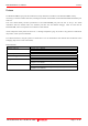
M301N2T-PRB User’s Manual 1. Outline 1.4 Specifications Tables 1.5 lists the specifications of the M301N2T-PRB. Table 1.5 M301N2T-PRB specification Item Applicable MCU Evaluation MCU Usable MCU mode Applicable power supply Operating frequency 4.2--5.
M301N2T-PRB User’s Manual 1. Outline 1.5. Operating Environment Be sure to use this emulator with the operating environmental of the emulator and host machine listed in Tables 1.6 and 1.7. Table 1.6 Operating environmental conditions Item Operating temperature 5 to 35°C (no dew) Storage temperature -10 to 60°C (no dew) Description Table 1.
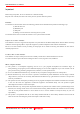
M301N2T-PRB User’s Manual 2. Setup 2. Setup This chapter describes the preparation for using this product, the procedure for starting up the emulator and how to change settings. 2.1 Selecting Clock Supply 2.1.1 Clock Supply to the MCU There are two ways to supply a clock to the MCU, using the oscillator circuit of the emulation pod or using the oscillator circuit on the user system. Table 2.1 lists the factory-settings of each clock supply when you install the emulator debugger. Table 2.
M301N2T-PRB User’s Manual 2. Setup Figure 2.1 External oscillator circuit Make note that in the oscillator circuit shown in Figure 2.2 where a resonator is connected between pins XIN and XOUT, oscillation does not occur because a flexible cable, buffer IC and other devices are used between the evaluation MCU and the user system. It is same for sub-clock oscillator circuits (XCIN and XCOUT). Figure 2.2 Circuit in which oscillation does not occur (same for XCIN-XCOUT) REJ10J0037-0100 Rev.1.00 Mar.
M301N2T-PRB User’s Manual 2. Setup 2.2 Switch Settings It is necessary to set the switches of the FLX64-PRB for debugging according to the user system. Figure 2.3 shows the positions of the switches of the FLX64-PRB, and Table 2.2 shows the switch settings. FLX64-PRB board PO RT JP1 XC IN NC PO R T JP2 Figure 2.3 Positions of the switches and their factory-settings Table 2.
M301N2T-PRB User’s Manual 2. Setup 2.3 A/D and D/A Conversion Bypass Capacitors This product has a foot pattern on the board for mounting a bypass capacitor for the A/D and D/A converter circuits. Mount a suitable bypass capacitor as occasion demands. Figure 2.4 shows the position of the bypass capacitor. 40 50 51 I C1 21 26 1 25 J1 VREF-VSS C6 75 76 M301N2T-PRB REV.A 1 100 40 20 J2 C6 MADE I N JAPAN 1 21 20 Figure 2.
M301N2T-PRB User’s Manual 2. Setup 2.4 Connection the M30100T3-RPD-E The emulation pod for the M16C/1N Group MCUs consists of the two products, the M30100T3-RPD-E emulation pod main unit and the M301N2T-PRB pod probe. Figures 2.5 and 2.6 show how to connect the M301N2T-PRB and how to remove it, respectively. FLX6 4 - PRB (1) Connect connectors J1 and J2 of the M301N2T-PRB to connectors J3 and J4 of the FLX64-PRB. M301N2T-PRB Screw (x2) (2) Fix the FLX64-PRB by the two screws. Figure 2.
M301N2T-PRB User’s Manual 2. Setup 2.5 Connecting the User System Connect the emulation pod to the user system as shown in Figure 2.7. Emulation pod M30100T3-RPD-E Pod probe M301N2T-PRB M30102T-PTC 48-pin 0.5-mm-pitch LQFP : No.1 pin User system Figure 2.7 Connecting the user system REJ10J0037-0100 Rev.1.00 Mar.
M301N2T-PRB User’s Manual 2. Setup Figures 2.8 shows how to connect converter board M30102T-PTC for a 48-pin 0.5-mm-pitch package. NQP ACK 0 4 8 SD (1) Mount the NQPACK048SD to the user system. : No. 1 pin YQ - GUI DE YQP A C K 0 4 8 SD NQPACK 0 4 8 SD (2) Connect the YQPACK048SD to the NQPACK048SD using the YQ-GUIDE's. (As the screws included with the YQPACK048SD are used for the HQPACK048SD, do not use them for securing the YQPACK048SD.) : No.
M301N2T-PRB User’s Manual 3. Usage 3. Usage This chapter describes the setting when you use this product for the first time and the workflow, from turning on the power of this product to starting up the emulator debugger. 3.1 When Using This Product for the First Time 3.1.1 Making an MCU File It is necessary to make an MCU file to use this product with the emulator debugger. According to the MCU you use, change the contents of the MCU file.
M301N2T-PRB User’s Manual 3. Usage 3.2 Turning On the Power 3.2.1 Checking Connections of the Emulator System Before turning the power ON, check the connections of the PC4701, emulation pod, pod probe, converter board and user system. 3.2.2 Turning ON/OFF the Power (1) Turn on the power of the emulator and user system as simultaneously as possible. (2) Turn off the power of the emulator and user system as simultaneously as possible.
M301N2T-PRB User’s Manual 3. Usage 3.2.3 LED Display When the Emulator Starts Up Normally After the emulator starts up, check the status of the LEDs on the front panel to see whether emulation pod operation is enabled or not. Figure 3.1 shows front panel LED lighting status when the emulator is turned ON. - When this does not light, check the power supply of the user system. - Check that power is supplied to all the terminals. - This does not light when the user system is not connected.
M301N2T-PRB User’s Manual 3. Usage 3.3 Downloading Firmware 3.3.1 When It is Necessary to Download Firmware It is necessary to download the firmware in the cases listed below. Normally, the following are automatically detected when the emulator debugger is started up, and the firmware is downloaded.
M301N2T-PRB User’s Manual 3. Usage 3.4 Self-check 3.4.1 Self-check Procedure To run the self-check of the emulator, do so as explained here below. While the self-check is in progress, the LEDs will change as shown in Figure 3.5. (1) (2) (3) (4) (5) (6) If the user system is connected, disconnect it. Set the switches in the emulation pod to the factory settings as shown in Figure 3.3. Set the switches in the emulation pod FLX64-PRB to the factory settings as shown in Figure 3.4.
M301N2T-PRB User’s Manual 3. Usage 3.4.2 If an Error is Detected in the Self-check If the self-check does not result normally (system status error or target status error in Figure 3.5), check the following. Whether the emulation pod and PC4701 are connected properly Whether the pod probe and emulation pod are connected properly Redownload the proper firmware Whether the switches in the M30100T3-RPD-E and FLX64-PRB are set to the factory settings (as shown in Figure 3.3 and Figure 3.4).
M301N2T-PRB User’s Manual POWER P OWE R S AFE ERROR S T A T US O F 3.
M301N2T-PRB User’s Manual 4. Hardware Specifications 4. Hardware Specifications This chapter describes specifications of this product. 4.1 Target MCU Specifications Table 4.1 lists the specifications of target MCUs which can be debugged with this product. Table 4.1 Specifications of target MCUs for the M301N2T-PRB Item Description Applicable MCU M16C/1N Group Applicable MCU mode Single-chip mode Emulation Memory 1 MB Max. operating frequency 16MHz (VCC2=4.2--5.5 V) Operating voltage VCC=4.2--5.
M301N2T-PRB User’s Manual 4. Hardware Specifications 4.2 Differences between the Actual MCU and Emulator Differences between the actual MCU and emulator are shown below. When debugging the MCU using this product, be careful about the following precautions. IMPORTANT Note on Differences between the Actual MCU and Emulator: Operations of the emulator system differ from those of actual MCUs as listed below. (1) Reset condition Set the time for starting up (0.2 Vcc to 0.8 Vcc) 1 μs or less.
M301N2T-PRB User’s Manual 4. Hardware Specifications IMPORTANT Note on RESET* Input: "L" level input from the user system to pin RESET* is accepted only while a user program is being executed (only while the RUN status LED on the PC4701's front panel is lit). Notes on Maskable Interrupts: Even if a user program is not being executed (including when run-time debugging is being performed), the evaluation MCU keeps running so as to control the emulation pod.
M301N2T-PRB User’s Manual 4. Hardware Specifications 4.3 External Dimensions 4.3.1 External Dimensions of the Pod Probe Figure 4.1 shows external dimensions of the M301N2T-PRB. 14. 1 55 40 50 I C1 26 1 25 J1 20 40 51 21 75 76 1 100 40 M301N2T-PRB REV.A J2 C6 MADE I N JAPAN 1 21 20 Unit: mm Figure 4.1 External dimensions of the M301N2T-PRB 4.3.2 External Dimensions of the Converter Board M30102T-PTC Figure 4.
M301N2T-PRB User’s Manual 4. Hardware Specifications 4.4 Notes on Using This Product Notes on using this product are listed below. Be sure to read these notes before using this product. IMPORTANT Note on Malfunctions in the PC4701 System If the emulator malfunctions because of interference like external noise, do the following to remedy the trouble (1) Press the RESET switch on the emulator front panel.
M301N2T-PRB User’s Manual 4. Hardware Specifications IMPORTANT Note on Clock Supply to the MCU: A clock supplied to the evaluation MCU is selected by the Clock tab in the Init dialog box of the emulator debugger. (1) When "Internal" is selected: A clock generated by the oscillation circuit in the emulation pod is supplied to the evaluation MCU. The clock is continually supplied to the evaluation MCU regardless of a status of user system clock and a status of user program execution.
M301N2T-PRB User’s Manual 4. Hardware Specifications IMPORTANT Notes on Address-Match Interrupts: To debug address-match interrupts, set a software break or hardware break at the top address of the address-match interrupt process. If you set a software break or hardware break at an address where an address-match interrupt occurs, the program may run out of control.
M301N2T-PRB User’s Manual 4. Hardware Specifications IMPORTANT Note on Instructions that Access the Single-step Interrupt Vector Area: Do not perform the below debugging operations with the single-step interrupt vector area (addresses FFFECh--FFFEFh). (1) Step execution of instructions that access the single step interrupt vector area (2) Program execution from the instruction accessing the single step interrupt vector area when a software breakpoint is set at the instruction REJ10J0037-0100 Rev.1.
M301N2T-PRB User’s Manual 5. Troubleshooting 5. Troubleshooting This chapter describes how to troubleshoot when this product does not work properly. 5.1 Flowchart to Remedy the Troubles Figure 5.1 shows the flowchart to remedy troubles from when power to the emulator is activated until the emulator debugger starts up. Check this while the user system is not connected. For the latest FAQs visit the Renesas Tools Homepage. http://www.renesas.
M301N2T-PRB User’s Manual 5. Troubleshooting 5.2 When the Emulator Debugger Does Not Start Up Properly 5.2.1 When the LED Display of the PC4701 is Abnormal Table 5.1 LED's abnormal display and its checkpoints Connection to Error Checkpoint the user system Check that the power cable is connected to the PC4701. LEDs do not light up. See the PC4701 user's manual All LEDs remain lit. The "POWER" LED of "STATUS OF TARGET" does not light up.
M301N2T-PRB User’s Manual 5. Troubleshooting 5.2.2 Emulator Debugger Does Not Starts Up Properly (Target Connected) Table 5.2 Checkpoints of errors when starting up the emulator debugger (target connected) Error Checkpoint ERROR 16005: (1) Check the connection between the PC4701 and host machine. Can't connect with the target. See the PC4701 User's Manual (2) Check that the PC4701 is powered on.
M301N2T-PRB User’s Manual 5. Troubleshooting 5.2.3 Emulator Debugger Does Not Starts Up Properly (Target Not Connected) Table 5.3 Checkpoints of errors when starting up the emulator debugger (target not connected) Error Checkpoint ERROR 16005: (1) Check the connection between the PC4701 and host machine. Can't connect with the target. See the PC4701 User's Manual (2) Check that the PC4701 is powered on.
M301N2T-PRB User’s Manual 5. Troubleshooting 5.3 How to Request for Support After checking the items in "5 Troubleshooting", fill in the text file the installer of the emulator debugger generates in the following directory and email to your local distributor. \SUPPORT\product-name\SUPPORT.
M301N2T-PRB User’s Manual 6. Maintenance and Guarantee 6. Maintenance and Guarantee This chapter describes how to maintenance, repair provisions and how to request for repair. 6.1 Maintenance (1) If dust or dirt collects on any equipment of your emulation system, wipe it off with a dry soft cloth. Do not use thinner or other solvents because these chemicals can cause the equipment's surface coating to separate.
M301N2T-PRB User’s Manual 6. Maintenance and Guarantee 6.4 How to Make Request for Repair If your product is found faulty, follow the procedure below to send your product for repair. Customer Fill in the Repair Request Sheet included with this product, then send it along with this product for repair to your local distributor. Make sure that information in the Repair Request Sheet is written in as much detail as possible to facilitate repair.
Pod probe for M16C/1N Group M301N2T-PRB User’s Manual Publication Date: Mar. 16, 2005 Published by: Edited by: Rev.1.00 Sales Strategic Planning Div. Renesas Technology Corp . Microcomputer Tool Development Department Renesas Solutions Corp. © 2005. Renesas Technology Corp. and Renesas Solutions Corp., All rights reserved. Printed in Japan.
M301N2T-PRB User's Manual