M37906T-PRB Pod Probe for 7906 Group MCUs User's Manual Rev.1.
• AXS69204201 is a product of Matsushita Electric Works, Ltd. Keep safety first in your circuit designs! • Renesas Technology Corporation and Renesas Solutions Corporation put the maximum effort into making semiconductor products better and more reliable, but there is always the possibility that trouble may occur with them. Trouble with semiconductors may lead to personal injury, fire or property damage.
Preface The M37906T-PRB is a pod probe for the 7906 Group of Renesas 16-bit microcomputers. The M37906T-PRB is used by connecting to the PC4701 emulator main unit and the M37900T2-RPD-E emulation pod main unit (option). This manual mainly explains specifications and how to set up the M37906T-PRB. For detail information about the emulator main unit, emulation pod main unit, and emulator debugger, refer to each user's manual.
Contents Chapter 1. Precautions for Safety ........................................................................................... 7 1.1 Safety Symbols and Meanings .............................................................................. 8 Warning for Installation ................................................................................... 9 Warning for Use Environment .........................................................................
Chapter 4. Specifications ...................................................................................................... 27 4.1 Specifications ...................................................................................................... 28 4.2 Electrical Characteristics ..................................................................................... 28 4.3 Connection Diagram ........................................................................................... 29 4.
MEMO ( 6 / 40 )
Chapter 1. Precautions for Safety This chapter describes precautions for using this product safely and properly. For precautions for the emulator main unit, the emulation pod main unit and the emulator debugger, refer to each user's manual included with your product. 1.1 Safety Symbols and Meanings ..................................................................................................... 8 WARNING Warning for Installation ........................................................................
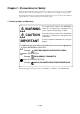
Chapter 1. Precautions for Safety In both the user's manual and on the product itself, several icons are used to insure proper handling of this product and also to prevent injuries to you or other persons, or damage to your properties. This chapter describes the precautions which should be taken in order to use this product safely and properly. Be sure to read this chapter before using this product. 1.
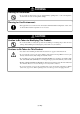
WARNING Warning for Installation: • Do not set this product in water or areas of high humidity. Spilling water or some other liquid into the main unit can cause an unrepairable damage. Warning for Use Environment: • This equipment is to be used in an environment with a maximum ambient temperature of 35°C. Care should be taken that this temperature is not exceeded. CAUTION Caution to Be Taken for Modifying This Product: • Do not disassemble or modify this product.
IMPORTANT Notes on Target System: • The Vcc pin of emulator is connected to the target system to observe the voltage of the target system. Therefore the emulator cannot supply the power to the target system. Design your system so that the target system is powered separately. • The voltage of the target system should be within the range of the MCU specification and suit to the emulator MCUs as shown below: - For 5.0V version MCUs: +4.5 to +5.
IMPORTANT Notes on EMEM Dialog: • When setting the EMEM dialog box of emulator debugger M3T-PD79, pay attention to the following: (1) Processor Mode Specify a processor mode for the target MCU to be debugged. With 7906 Group MCUs, only the single-chip mode is specifiable. If the MD0 pin setting is not "L" level, emulator debugger M3T-PD79 outputs an error message. In such a case, check the pin settings on the target system.
IMPORTANT Note on Interface with the Target System: • The pin that connects to the target system is pulled-up by the emulation pod probe using local resistors. For the difference in electric characteristics between the actual MCU and the emulator, see "Chapter 4. Specifications" (page 27). Pullup resistors of Init4* pin To avoid high impedance, this pin is pulled-up with a 510kΩ resistor. These pullup resistors cannot be removed.
IMPORTANT Note on Differences between Actual MCU and Emulator: • Operations of the emulator differs from those of mask MCUs as listed below. (1) Initial values of internal resource data (such as a part of SFR, and RAM) at power-on (2) Oscillator circuit Make note of the fact that in the oscillator circuit where a resonator is connected between the XIN and XOUT pins, oscillation does not occur because a flexible cable, buffer IC and other devices are used between the emulator MCU and the target system.
MEMO ( 14 / 40 )
Chapter 2. Preparation This chapter describes the package components, the system configuration and the preparation for using this product for the first time. 2.1 Terminology ............................................................................................................................... 16 2.2 Package Components.................................................................................................................. 17 2.3 Other Tool Products Required for Development.................
Chapter 2. Preparation 2.1 Terminology Some specific words used in this user's manual are defined as follows: Emulator system This means an emulator system built around the PC4701 emulator. The PC4701 emulator system is configured with an emulator main unit, emulation pod, pod probe, host machine and emulator debugger. Emulator main unit (Hereafter PC4701) This means a generic name for emulators for 8 and 16-bit MCUs. For details on specific models of PC4701, visit Renesas Tools Homepage at http://www.
2.2 Package Components This product consists of the following items. When unpacking, check to see if your product package contains all of these items.
2.4 System Configuration Figure 2.1 System configuration Products (2) and (3) shown in Figure 2.1 are included with this product. Get (1) in Figure 2.1 separately. (1) Emulation pod main unit (M37900T2-RPD-E) This is an emulation pod common for 7900 Series MCUs. By replacing the pod probe on the tip of the emulation pod, it will support future 7900 Series MCUs (option). (2) Pod probe (M37906T-PRB) This pod probe is equipped with the emulator MCU, M37906FCCWP. (3) Pitch converter board for 42-pin 0.
Chapter 3. Setting Up This chapter describes switch settings required for using this product and how to connect this product to the PC4701 and the target system. 3.1 Switch Settings ........................................................................................................................... 20 3.2 A-D Conversion Bypass Capacitor ............................................................................................ 21 3.3 Connecting the Emulation Pod Main Unit ..........................
Chapter 3. Setting Up With this product, it is necessary to set the following according to your target system. • Setting switches • Mounting the A-D conversion bypass capacitor 3.1 Switch Settings It is necessary to set the switches of the M37906T-PRB for debugging according to the target system. Figure 3.1 shows the positions of the switches of the M37906T-PRB, and Table 3.1 shows the switch settings. Figure 3.1 Positions of the switches and their factory-settings Table 3.
3.2 A-D Conversion Bypass Capacitor This product has foot patterns on the board for mounting a bypass capacitor for the A-D converter circuit. Mount a suitable bypass capacitor as occasion demands. Figure 3.2 shows the position of the bypass capacitor. Figure 3.
3.3 Connecting the Emulation Pod Main Unit The emulation pod for 7906 Group MCUs consists of the following two products. (1) Emulation pod (2) Pod probe : M37900T2-RPD-E : M37906T-PRB It is necessary to connect the M37906T-PRB to the M37900T2-RPD-E for the emulation of 7906 Group MCUs. Figure 3.3 shows how to connect them. (1) Unscrew the four screws of M37906T-PRB. (2) Connect the connectors J3 and J4 of the M37900T2RPD-E's FLX100 to the connectors J3 and J4 of the M37906T-PRB.
With the 7900 Series emulator system, the internal flash ROM of the emulator MCU is used as an emulation memory. As write/erase iterations to the internal ROM are limited, it is necessary to replace the MCU board (M37906T-PRBM) depending on its life span. How to replace the MCU board is shown in Figure 3.4. (1) Unscrew the four screws of M37906T-PRB. (2) Remove the M37906T-PRBM from the M37906T-PRB. In this time, lift off the M37906T-PRBM horizontally. Otherwise, the connector may cause a break. Figure 3.
3.4 Connecting the Target System There are three ways available to connect the emulation pod to target systems as shown in Figure 3.5. *1 : These three products are available in a single package. *2 : This converter board is included in this pod probe package. : position of No. 1 pin Figure 3.
Figure 3.6 shows how to connect the pitch converter board SSOP42B-450 for 42-pin 0.8mm-pitch SSOP. (1) Mount the SSOP socket AXS69204201 (made by Matsushita Electric Works, Ltd.) on the target system. (2) Attach the SSOP42B-450 to the AXS69204201. (3) Connect the M37906T-PRB to the SSOP42B-450. Figure 3.6 Connecting the pitch converter board SSOP42B-450 for 42-pin 0.8mm-pitch SSOP CAUTION Notes on Connecting the Target System: • Always shut OFF power before connecting the target system.
MEMO ( 26 / 40 )
Chapter 4. Specifications This chapter describes specifications of this product. 4.1 Specifications ............................................................................................................................. 28 4.2 Electrical Characteristics ............................................................................................................ 28 4.3 Connection Diagram ...................................................................................................................
Chapter 4. Specifications 4.1 Specifications Table 4.1 lists the specifications of the M37906T-PRB. Table 4.1 Specifications of M37906T-PRB Emulators PC4701 Emulation pod main unit M37900T2-RPD-E Applicable MCUs 7906 Group MCUs Emulator MCU M37906FCCWP (pre-mounted on the M37906T-PRBM) Usable MCU mode Single-chip mode Max. operating frequency 20MHz Running mode Clock supply Internal oscillator board, switchable to an external oscillator Min. instruction execution time Approx.
4.3 Connection Diagram Figure 4.1 shows the connection diagram of the emulation pod for 7906 Group (M37900T2-RPD-E and M37906T-PRB). This connection diagram mainly shows the interface section, and the circuits which are not connected to the target system such as the emulator's control system are omitted. Figure 4.
4.4 External Dimensions of Pod Probe Figure 4.2 shows the external dimensions of M37906T-PRB. Unit: mm Figure 4.
Chapter 5. Troubleshooting This chapter describes how to troubleshoot when this product does not work properly. 5.1 When the Emulator Debugger Does Not Operate ...................................................................... 32 (1) Errors Occur When Operating the Emulator Debugger (When the target system is connected) ........................................................ 32 (2) Errors Occur When Operating the Emulator Debugger (When the target system is not connected) ............................
Chapter 5. Troubleshooting When this product does not work properly, check the following. 5.1 When the Emulator Debugger Does Not Operate (1) Errors Occur When Operating the Emulator Debugger (When the target system is connected) Table 5.
(2) Errors Occur When Operating the Emulator Debugger (When the target system is not connected) Table 5.2 Checkpoints of errors when starting up the emulator debugger M3T-PD79 (target is not connected) Error Checkpoint Check all emulator debugger settings, interface cable connections and switches on the rear of the PC4701 match. Communication ERROR Data is not sent to the target - See the user's manuals of the PC4701 and emulator debugger.
MEMO ( 34 / 40 )
Chapter 6. Maintenance and Warranty This chapter describes how to maintenance, repair provisions and how to request for repair. 6.1 Maintenance ............................................................................................................................... 36 6.2 Warranty ..................................................................................................................................... 36 6.3 Repair Provisions................................................................
Chapter 6. Maintenance and Guarantee 6.1 Maintenance If dust or dirt collects on any equipment of your emulation system, wipe it off with a dry soft cloth. Do not use thinner or other solvents because these chemicals can cause the equipment's surface coating to separate. 6.
6.4 How to Request for Repair If your product is found faulty, follow the procedure below to send your product for repair. Customer Fill in the Repair Request Sheet included with this product, then send it along with this product for repair to your local distributor. Make sure that information in the Repair Request Sheet is written in as much detail as possible to facilitate repair.
MEMO ( 38 / 40 )
M37906T-PRB User's Manual Rev.1.