REJ10J1776-0100 SH7286 Group PLQP0176KB-A User System Interface Board R0E572860CFK00 User’s Manual Renesas Microcomputer Development Environment System SuperH™ Family / SH7280 Series Rev.1.00 Revision Date: Jan.
Notes regarding these materials 1. This document is provided for reference purposes only so that Renesas customers may select the appropriate Renesas products for their use. Renesas neither makes warranties or representations with respect to the accuracy or completeness of the information contained in this document nor grants any license to any intellectual property rights or any other rights of Renesas or any third party with respect to the information in this document. 2.
IMPORTANT INFORMATION READ FIRST • READ this user's manual before using this emulator product. • KEEP the user's manual handy for future reference. Do not attempt to use the emulator product until you fully understand its mechanism. Emulator Product: Throughout this document, the term "emulator product" shall be defined as the following products produced only by Renesas Technology Corp. and Renesas Solutions Corp. excluding all subsidiary products.
Target User of the Emulator Product: This emulator product should only be used by those who have carefully read and thoroughly understood the information and restrictions contained in the user's manual. Do not attempt to use the emulator product until you fully understand its mechanism. It is highly recommended that first-time users be instructed by users that are well versed in the operation of the emulator product.
LIMITED WARRANTY Renesas warrants its emulator products to be manufactured in accordance with published specifications and free from defects in material and/or workmanship. Renesas, at its option, will replace any emulator products returned intact to the factory, transportation charges prepaid, which Renesas, upon inspection, shall determine to be defective in material and/or workmanship. The foregoing shall constitute the sole remedy for any breach of Renesas’ warranty.
State Law: Some states do not allow the exclusion or limitation of implied warranties or liability for incidental or consequential damages, so the above limitation or exclusion may not apply to you. This warranty gives you specific legal rights, and you may have other rights which may vary from state to state.
SAFETY PAGE READ FIRST • READ this user's manual before using this emulator product. • KEEP the user's manual handy for future reference. Do not attempt to use the emulator product until you fully understand its mechanism. DEFINITION OF SIGNAL WORDS Either in the user's manual or on the product, several icons are used to insure proper handling of this product and also to prevent injuries to you or other persons, or damage to your properties. Their graphic images and meanings are given in this safety page.
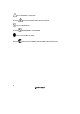
means WARNING or CAUTION. Example: CAUTION AGAINST AN ELECTRIC SHOCK means PROHIBITION. Example: DISASSEMBLY PROHIBITED means A FORCIBLE ACTION. Example: VI UNPLUG THE POWER CABLE FROM THE RECEPTACLE.
WARNING Warnings for AC Power Supply: • If the attached AC power cable does not fit the receptacle, do not alter the AC power cable and do not plug it forcibly. Failure to comply may cause electric shock and/or fire. • Use an AC power cable which complies with the safety standard of the country. • Do not touch the plug of the AC power cable when your hands are wet. This may cause electric shock. • This product is connected signal ground with frame ground.
WARNING • If you smell a strange odor, hear an unusual sound, or see smoke coming from this product, then disconnect power immediately by unplugging the AC power cable from the outlet. Do not use this as it is because of the danger of electric shock and/or fire. In this case, contact your local distributor. • When installing or connecting this product with other equipment, shut down AC power or disconnect the AC power cord from the equipment to prevent personal injury or damage to the equipment.
CAUTION Cautions for AC Adapter: • Use only the AC adapter included in this product package. • The included AC adapter is for this emulator. Do not use it for other product. • The DC plug on the included AC adapter has the below polarity. • The included AC adapter has no power supply switch. The AC adapter is always active while connecting the AC power cable. Cautions to Be Taken for This Product: • Use caution when handling this product. Be careful not to apply a mechanical shock.
WARNING Observe the precautions listed below. Failure to do so will result in a FIRE HAZARD and will damage the user system and the emulator product or will result in PERSONAL INJURY. The USER PROGRAM will be LOST. 1. Do not repair or remodel the emulator product by yourself for electric shock prevention and quality assurance. 2. Always switch OFF the E200F emulator and user system before connecting or disconnecting any CABLES or PARTS. 3.
Preface The R0E572860CFK00 is a user system interface board that connects a user system for the SH7286 PLQP0176KB-A (former package: FP-176EV) package to the SH7280 E200F emulator (R0E0200F1EMU00 or R0E572800VKK00).
Contents Section 1 Configuration.....................................................................................1 Section 2 Environmental Conditions.................................................................3 Section 3 Connection Procedures ...................................................................... 4 3.1 3.2 3.3 3.4 3.5 Connecting User System Interface Board to User System................................................ 4 3.1.1 Installing IC Socket .................................
Section 1 Configuration Figure 1 and table 1 show the external appearance and components, respectively, of the user system interface board for the PLQP0176KB-A. Please make sure you have all of these components when unpacking. Screws (M2.0 x 6 mm) EV-chip unit Screws (M2.
CAUTION Use a NQPACK176SD socket (manufactured by Tokyo Eletech Corporation) and a HQPACK176SD (manufactured by Tokyo Eletech Corporation) for the PLQP0176KB-A package IC socket and socket cover, respectively, on the user system. Table 1 R0E572860CFK00 Components No. Component Quantity Remarks 1 Board 1 With four spacers (2.
Section 2 Environmental Conditions Maintain the conditions in table 2 when using the emulator. Table 2 Environmental Conditions Item Specifications Temperature Operating: +10 to +35°C Storage: -10 to +35°C Humidity Operating: 35 to 80% RH, no condensation Storage: 35 to 80% RH, no condensation Vibration Operating: 2.45 m/s max. 2 Storage: 4.9 m/s max. 2 Transportation: 14.7 m/s max. Ambient gases There must be no corrosive gases present.
Section 3 Connection Procedures 3.1 Connecting User System Interface Board to User System WARNING Always switch OFF the user system and the emulator product before the USER SYSTEM INTERFACE BOARD is connected to or removed from any part. Before connecting, make sure that pin 1 on both sides are correctly aligned. Failure to do so will result in a FIRE HAZARD and will damage the user system and the emulator product or will result in PERSONAL INJURY. The USER PROGRAM will be LOST.
3.1.2 Installing Cable Head CAUTION Check the location of pin 1 before inserting. Align pin 1 on the IC socket for a PLQP0176KB-A package on the user system with pin 1 on the user system interface board, and insert the user system interface board into the IC socket on the user system, as shown in figure 2. 3.1.3 Fastening Cable Head CAUTION 1. Use a Phillip-type screwdriver whose head matches the screw head. 2. The tightening torque must be 0.054 N•m or less.
Fasten the user system interface board to the IC socket for a PLQP0176KB-A package on the user system with the four screws (M2.0 x 10 mm) provided. Each screw should be tightened a little at a time, alternating between screws on opposing corners. Take special care, such as manually securing the IC socket soldered area, to prevent the soldered IC socket from being damaged by overtightening the screws or twisting the components. Screws (M2.
3.2 Connecting User System Interface Board to EV-Chip Board WARNING Observe the precautions listed below. Failure to do so will result in a FIRE HAZARD and will damage the user system and the emulator product or will result in PERSONAL INJURY. The USER PROGRAM will be LOST. 1. Always switch OFF the user system and the emulator product before the USER SYSTEM INTERFACE BOARD is connected to or removed from any part. Before connecting, make sure that pin 1 on both sides are correctly aligned. 2.
EV-chip unit Connector No. EV-Chip Unit Connector No. User I/F Connector 1 (CN4) User I/F Connector 2 (CN5) Board Connector No.
3.3 Recommended Dimensions for User System Mount Pad (Footprint) Figure 4 shows the recommended dimensions for the mount pad (footprint) for the user system with an IC socket for a PLQP0176KB-A package (NQPACK176SD: manufactured by Tokyo Eletech Corporation). Note that the dimensions in figure 4 are somewhat different from those of the actual chip's mount pad. 27.10 min 23.10 max 0.50 × 43 = 21.50 ± 0.30 0.50 ± 0.05 Pin 1 0.25 ± 0.05 0.50 × 43 = 21.5 ± 0.30 10.0 ± 0.2 0.5 ± 0.05 10.0 ± 0.
3.4 Dimensions for External Bus Trace Unit, Emulation Memory Unit, EV-Chip Unit, and User System Interface Board The dimensions for the external bus trace unit, emulation memory unit, EV-chip unit, and the user system interface board are shown in figure 5.
90.0 125.0 External bus trace unit 90.0 125.0 110.0 90.0 20.0 Emulation memory unit 125.0 EV-chip unit 60.0 30.0 90.0 45.0 Pin 1 5.0 Spacer Board Unit: mm Tolerance: ±0.5 mm 5.
3.5 Resulting Dimensions after Connecting User System Interface Board The resulting dimensions, after connecting the user system interface board to the user system, are shown in figures 6, 7, and 8. External bus trace unit Emulation memory unit 12.5 29.2 55.0 68.4 EV-chip unit 24.5 30.0 37.5 27.5 Spacer (φ6.0) User system 24.5 39.19 39.19 24.5 IC socket (NQPACK176SD manufactured by Tokyo Eletech Corporation) Pin 1 Unit: mm Tolerance: ±1.
External bus trace unit 12.5 42.1 29.2 55.5 EV-chip unit 24.5 37.5 27.5 30.0 Spacer (φ6.0) User system 24.5 39.19 39.19 24.5 IC socket (NQPACK176SD manufactured by Tokyo Eletech Corporation) Pin 1 Unit: mm Tolerance: ±1.
12.5 29.2 42.6 EV-chip unit 24.5 37.5 27.5 30.0 Spacer (φ6.0) User system 24.5 39.19 39.19 24.5 IC socket (NQPACK176SD manufactured by Tokyo Eletech Corporation) Pin 1 Unit: mm Tolerance: ±1.
Section 4 Installing the MCU to the User System CAUTION 1. Check the location of pin 1 before inserting. 2. Use a Philips-type screwdriver whose head matches the screw head. 3. The tightening torque must be 0.054 N•m or less. If the applied torque cannot be accurately measured, stop tightening when the force required to turn the screw becomes significantly greater than that needed when first tightening.
Screws (M2.
Section 5 Verifying Operation 1. Turn on the emulator according to the procedures described in the SH-2A, SH-2 E200F Emulator User's Manual (R0E0200F1EMU00E or R0E572800EMU00E). 2. The emulator connected to this user system interface board supports three kinds of clock sources as the MCU clock. For details, refer to the SH7080 E200F Emulator User's Manual (R0E0200F1EMU00E). ⎯ To use the emulator internal clock Select the clock in the emulator by the CLOCK command (emulator command).
Section 6 Notice 1. Before connecting any parts or cables, make sure that pin 1 on the both sides are correctly aligned. 2. Do not apply excessive force to the user system interface board while it is connected to the user system. 3. The dimensions of the recommended mount pad for the IC socket for this user system interface board are different from those of the MCU. 4. This user system interface board is specifically designed for the SH7280 E200F EV-chip unit (R0E572800VKK00).
SH7286 Group PLQP0176KB-A User System Interface Board User's Manual Publication Date: Rev.1.00, January 9, 2008 Published by: Sales Strategic Planning Div. Renesas Technology Corp. Edited by: Customer Support Department Global Strategic Communication Div. Renesas Solutions Corp. © 2008. Renesas Technology Corp., All rights reserved. Printed in Japan.
Sales Strategic Planning Div. Nippon Bldg., 2-6-2, Ohte-machi, Chiyoda-ku, Tokyo 100-0004, Japan RENESAS SALES OFFICES http://www.renesas.com Refer to "http://www.renesas.com/en/network" for the latest and detailed information. Renesas Technology America, Inc. 450 Holger Way, San Jose, CA 95134-1368, U.S.A Tel: <1> (408) 382-7500, Fax: <1> (408) 382-7501 Renesas Technology Europe Limited Dukes Meadow, Millboard Road, Bourne End, Buckinghamshire, SL8 5FH, U.K.
SH7286 Group PLQP0176KB-A User System Interface Board User’s Manual