
Specifications

74
SINGLE-CHIP 8-BIT CMOS MICROCOMPUTER
7560 Group
MITSUBISHI MICROCOMPUTERS
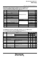
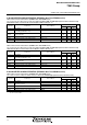
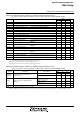
A-D CONVERTER CHARACTERISTICS (EPROM or One Time PROM version)
Table 36 A-D converter characteristics (EPROM or One Time PROM version)
(VCC = 2.7 to 5.5 V, VSS = AVSS = 0 V, Ta = –20 to 85°C, f(XIN) = 500 kHz to 8 MHz, in middle/high-speed mode unless otherwise noted)
8-bit A-D mode (when conversion mode selection bit (bit 0 of address 001416) is “1”)
Symbol Parameter
Limits
Min.
Unit
Typ. Max.
Test conditions
–
Resolution
Absolute accuracy
(excluding quantization error)
VCC = VREF = 2.7 to 5.5 V
Bits
LSB
35
150
8
±2
tc(ADCLK)
(Note)
Conversion time
Ladder resistor
Reference power source input current
–
tCONV
RLADDER
IVREF
kΩ
µA
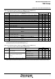
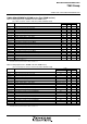
D-A CONVERTER CHARACTERISTICS (EPROM or One Time PROM version)
Table 38 D-A converter characteristics (EPROM or One Time PROM version)
(VCC = 2.7 to 5.5 V, VCC = VREF, VSS = AVSS = 0 V, Ta = –20 to 85°C, in middle/high-speed mode unless otherwise noted)
Symbol Parameter
Limits
Min.
Unit
Typ. Max.
Test conditions
–
Resolution
VCC = VREF = 5 V
VCC = VREF = 2.7 V
1
Bits
%
%
µs
kΩ
mA
3
2.5
8
1.0
2.0
Note: Using one D-A converter, with the value in the D-A conversion register of the other D-A converter being “0016”, and excluding currents flowing through
the A-D resistance ladder.
(Note)
Setting time
Output resistor
–
tsu
RO
4
3.2
12
50
Absolute accuracy
Analog port input currentIIA
IVREF Reference power source input current
µA
100
200
5.0
VREF = 5 V
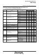
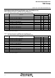
Table 37 A-D converter characteristics (EPROM or One Time PROM version)
(VCC = 2.7 to 5.5 V, VSS = AVSS = 0 V, Ta = –20 to 85°C, f(XIN) = 500 kHz to 8 MHz, in middle/high-speed mode unless otherwise noted)
10-bit A-D mode (when conversion mode selection bit (bit 0 of address 001416) is “0”)
49
50
Symbol Parameter
Limits
Min.
Unit
Typ. Max.
Test conditions
–
Resolution
Absolute accuracy
(excluding quantization error)
VCC = VREF = 2.7 to 5.5 V
Bits
LSB
35
150
10
±4
tc(ADCLK)
(Note)
Conversion time
Ladder resistor
Reference power source input current
–
tCONV
RLADDER
IVREF
kΩ
µA
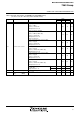
12
50
Analog port input currentIIA
µA
100
200
5.0
VREF = 5 V
61
62
Note: ADCLK is the control clock of the A-D converter. System clock
φ
is used.
Note: ADCLK is the control clock of the A-D converter. System clock
φ
is used.