
Specifications

SINGLE-CHIP 8-BIT CMOS MICROCOMPUTER
MITSUBISHI MICROCOMPUTERS
7560 Group
53
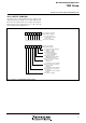
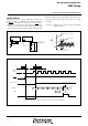
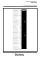
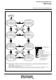
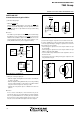
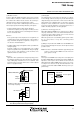
Fig. 58 Internal state of microcomputer immediately after reset
N
o
t
e
:
T
h
e
c
o
n
t
e
n
t
s
o
f
a
l
l
o
t
h
e
r
r
e
g
i
s
t
e
r
s
a
n
d
R
A
M
a
r
e
u
n
d
e
f
i
n
e
d
a
f
t
e
r
r
e
s
e
t
,
s
o
t
h
e
y
m
u
s
t
b
e
i
n
i
t
i
a
l
i
z
e
d
b
y
s
o
f
t
w
a
r
e
.
✕
:
U
n
d
e
f
i
n
e
d
R
eg
i
ster contents
A
d
d
r
e
s
s
0
0
0
1
1
6
0
0
0
31
6
000516
0
0
0
71
6
0
0
0
91
6
0
0
0
B
1
6
000
D
16
0
0
0
F
1
6
001416
001616
0
0
1
71
6
0
0
1
91
6
001
A
16
001
B
16
001
D
16
002016
0
0
2
11
6
0
0
2
21
6
0
0
2
31
6
002416
002516
0
0
2
61
6
0
0
2
71
6
002816
002916
0
0
2
A
1
6
0
0
2
B
1
6
0
0
3
21
6
003316
003416
003616
003716
0
0
3
81
6
0
0
3
91
6
003
A
16
003
B
16
003
C
16
003
D
16
0
0
3
E
1
6
003
F
16
(
P
S
)
(PC
H
)
(PC
L
)
(
1
0
)
(
1
1
)
(
1
2
)
(
1
3
)
(
1
4
)
(
1
5
)
(
16
)
(
1
7
)
(
18
)
(
1
9
)
(
2
0
)
(
2
1
)
(
22
)
(
23
)
(
2
4
)
(
2
5
)
(
26
)
(
27
)
(
2
8
)
(
2
9
)
(
3
0
)
(
31
)
(
32
)
(
3
3
)
(
3
4
)
(
1
)
(
2
)
(
3
)
(
4
)
(
5
)
(
6
)
(
7
)
(
8
)
(
9
)
(
3
5
)
(
3
6
)
(
3
7
)
(
38
)
(
39
)
(
40
)
(
4
1
)
(
4
2
)
(
4
3
)
T
i
m
e
r
Y
l
o
w
-
o
r
d
e
r
r
e
g
i
s
t
e
r
P
o
r
t
P
5
d
i
r
e
c
t
i
o
n
r
e
g
i
s
t
e
r
P
o
r
t
P
6
d
i
r
e
c
t
i
o
n
r
e
g
i
s
t
e
r
P
U
L
L
r
e
g
i
s
t
e
r
B
T
i
m
e
r
Y
h
i
g
h
-
o
r
d
e
r
r
e
g
i
s
t
e
r
S
e
r
i
a
l
I
/
O
1
c
o
n
t
r
o
l
r
e
g
i
s
t
e
r
UART control register
T
i
m
e
r
X
h
i
g
h
-
o
r
d
e
r
r
e
g
i
s
t
e
r
Timer X low-order register
Timer X mode register
T
i
m
e
r
Y
m
o
d
e
r
e
g
i
s
t
e
r
Timer 123 mode register
S
e
r
i
a
l
I
/
O
1
s
t
a
t
u
s
r
e
g
i
s
t
e
r
P
o
r
t
P
7
d
i
r
e
c
t
i
o
n
r
e
g
i
s
t
e
r
A-D control register
S
e
g
m
e
n
t
o
u
t
p
u
t
e
n
a
b
l
e
r
e
g
i
s
t
e
r
L
C
D
m
o
d
e
r
e
g
i
s
t
e
r
P
U
L
L
r
e
g
i
s
t
e
r
A
Interrupt edge selection register
C
P
U
m
o
d
e
r
e
g
i
s
t
e
r
Interrupt request register 1
Interrupt request register 2
Interrupt control register 1
I
n
t
e
r
r
u
p
t
c
o
n
t
r
o
l
r
e
g
i
s
t
e
r
2
P
r
o
c
e
s
s
o
r
s
t
a
t
u
s
r
e
g
i
s
t
e
r
P
r
o
g
r
a
m
c
o
u
n
t
e
r
P
o
r
t
P
4
d
i
r
e
c
t
i
o
n
r
e
g
i
s
t
e
r
P
o
r
t
P
2
d
i
r
e
c
t
i
o
n
r
e
g
i
s
t
e
r
P
o
r
t
P
3
o
u
t
p
u
t
c
o
n
t
r
o
l
r
e
g
i
s
t
e
r
P
o
r
t
P
1
d
i
r
e
c
t
i
o
n
r
e
g
i
s
t
e
r
P
o
r
t
P
0
d
i
r
e
c
t
i
o
n
r
e
g
i
s
t
e
r
Timer 1 register
Timer 2 register
Timer 3 register
A
D
c
o
n
v
e
r
s
i
o
n
l
o
w
-
o
r
d
e
r
r
e
g
i
s
t
e
r
111000 00
100000 00
001111
11
10010 000
✕ 1✕✕✕✕✕✕
0
0
1
6
0016
0016
0
01
6
0
01
6
0
01
6
FF
16
0
01
6
0
01
6
0
01
6
0
01
6
0
01
6
0
01
6
0
01
6
0
01
6
FF
16
FF
16
0
01
6
0
01
6
0
01
6
3
F
1
6
0
01
6
0
01
6
0
01
6
0
01
6
0
01
6
0016
0
01
6
0
01
6
F
F
1
6
F
F
1
6
Contents of address FFFD
16
Contents of address FFFC16
D-
A
c
o
n
t
r
o
l
r
e
g
i
s
t
e
r
W
a
t
c
h
d
o
g
t
i
m
e
r
c
o
n
t
r
o
l
r
e
g
i
s
t
e
r
D
-
A
1
c
o
n
v
e
r
s
i
o
n
r
e
g
i
s
t
e
r
D-A2 conversion register
S
e
r
i
a
l
I
/
O
2
c
o
n
t
r
o
l
r
e
g
i
s
t
e
r
T
O
U
T
/φ
o
u
t
p
u
t
c
o
n
t
r
o
l
r
e
g
i
s
t
e
r
P
W
M
c
o
n
t
r
o
l
r
e
g
i
s
t
e
r
Watchdog timer (high-order)
(
44
)
Watchdog timer (low-order)
F
F
1
6
0116
0016
00010 000
3
F
16
F
F
1
6
(
4
5
)
001516
K
e
y
i
n
p
u
t
c
o
n
t
r
o
l
r
e
g
i
s
t
e
r
0
01
6
✕✕0000 10