
Specifications

SINGLE-CHIP 8-BIT CMOS MICROCOMPUTER
MITSUBISHI MICROCOMPUTERS
7560 Group
52
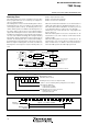
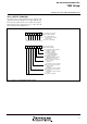
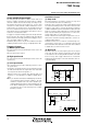
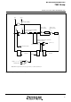
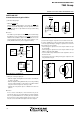
Fig. 56 Example of reset circuit
RESET CIRCUIT
When the power source voltage is within limits, and main clock
XIN-XOUT is stable, or a stabilized clock is input to the XIN pin, if
the RESET pin is held at an “L” level for 2 µs or more, the micro-
computer is in an internal reset state. Then the RESET pin is
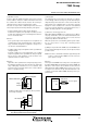
returned to an “H” level, reset is released after approximate 8200
cycles of f(XIN), the program in address FFFD16 (high-order byte)
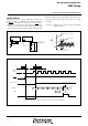
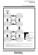
Fig. 57 Reset Sequence
and address FFFC16 (low-order byte). Make sure that the reset in-
put voltage is less than 0.2 VCC(min.) for the power source voltage
of V
CC(min.).
*V
CC(min.) = Minimum value of power supply voltage limits
applied to VCC pin
V
C
C
R
E
S
E
T
V
C
C
R
E
S
E
T
Power source
voltage detection
circuit
V
C
C
R
E
S
E
T
P
o
w
e
r
o
n
0
.
2
V
C
C
l
e
v
e
l
O
s
c
i
l
l
a
t
i
o
n
s
t
a
b
i
l
i
z
e
d
2
µs
X
I
N
0
V
0
V
0
V
(
N
o
t
e
)
N
o
t
e:
R
e
s
e
t
r
e
l
e
a
s
e
v
o
l
t
a
g
e
V
c
c
=
V
c
c
(
m
i
n
.
)
A
D
L
FFFC
FFFD
A
D
H
,
Undefined
X
I
N
:
A
p
p
r
o
x
.
8
2
0
0
c
y
c
l
e
s
N
o
t
e
:
T
h
e
f
r
e
q
u
e
n
c
y
o
f
s
y
s
t
e
m
c
l
o
c
k
φ
i
s
f
(
X
I
N
)
d
i
v
i
d
e
d
b
y
8
.
R
eset a
dd
ress
f
rom
vector table
R
E
S
E
T
I
n
t
e
r
n
a
l
r
e
s
e
t
Add
ress
D
ata
SYNC
S
y
s
t
e
m
c
l
o
c
k
φ
X
IN
AD
H
AD
L
Undefined U
n
d
e
f
i
n
e
dU
n
d
e
f
i
n
e
d