
Specifications

SINGLE-CHIP 8-BIT CMOS MICROCOMPUTER
MITSUBISHI MICROCOMPUTERS
7560 Group
39
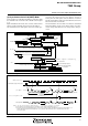
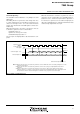
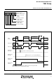
Fig. 39 PWM output timing when PWM register or PWM prescaler is changed
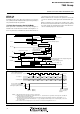
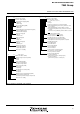
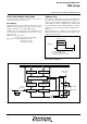
Fig. 38 Structure of PWM control register
b
7
b
0
P
W
M
c
o
n
t
r
o
l
r
e
g
i
s
t
e
r
(
P
W
M
C
O
N
:
a
d
d
r
e
s
s
0
0
2
B
1
6)
C
o
u
n
t
s
o
u
r
c
e
s
e
l
e
c
t
i
o
n
b
i
t
0:f
(
X
I
N)
1:f
(
X
I
N)
/
2
P
W
M
0
f
u
n
c
t
i
o
n
e
n
a
b
l
e
b
i
t
0:P
W
M
0
d
i
s
a
b
l
e
d
1:P
W
M
0
e
n
a
b
l
e
d
P
W
M
1
f
u
n
c
t
i
o
n
e
n
a
b
l
e
b
i
t
0:P
W
M
1
d
i
s
a
b
l
e
d
1:P
W
M
1
e
n
a
b
l
e
d
N
o
t
u
s
e
d
(
“
0
”
a
t
r
e
a
d
i
n
g
)
T
T2
C
B
T
PWM register
write signal
PWM prescaler
write signal
(Changes from “A” to “B” during “H” period)
(Changes from “T” to “T2” during PWM period)
PWM
(internal)
A
B
T
C
T2
=
stop
PWM0 function
enable bit
PWM1 function
enable bit
PWM
0 output
Port
Port
PWM1 output
Port
stop
Port
When the contents of the PWM register or PWM prescaler have changed, the PWM
output will change from the next period after the change.