
Specifications

SINGLE-CHIP 8-BIT CMOS MICROCOMPUTER
MITSUBISHI MICROCOMPUTERS
7560 Group
37
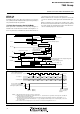
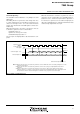
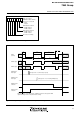
Fig. 35 Timing of serial I/O2 function
D
7
D
0
D
1
D
2
D
3
D
4
D
5
D
6
S
y
n
c
h
r
o
n
o
u
s
c
l
o
c
k
(
N
o
t
e
1
)
S
e
r
i
a
l
I
/
O
2
o
u
t
p
u
t
S
O
U
T
2
S
e
r
i
a
l
I
/
O
2
i
n
p
u
t
S
I
N
2
Serial I/O2 register
write signal
(
N
o
t
e
s
2
,
3
)
S
e
r
i
a
l
I
/
O
2
i
n
t
e
r
r
u
p
t
r
e
q
u
e
s
t
b
i
t
=
“
1
”
1
:
W
h
e
n
t
h
e
i
n
t
e
r
n
a
l
c
l
o
c
k
i
s
s
e
l
e
c
t
e
d
a
s
t
h
e
s
y
n
c
h
r
o
n
o
u
s
c
l
o
c
k
,
t
h
e
d
i
v
i
d
e
r
a
t
i
o
c
a
n
b
e
s
e
l
e
c
t
e
d
b
y
s
e
t
t
i
n
g
b
i
t
s
0
t
o
2
o
f
t
h
e
s
e
r
i
a
l
I
/
O
2
c
o
n
t
r
o
l
r
e
g
i
s
t
e
r
.
2
:
W
h
e
n
t
h
e
i
n
t
e
r
n
a
l
c
l
o
c
k
i
s
s
e
l
e
c
t
e
d
a
s
t
h
e
s
y
n
c
h
r
o
n
o
u
s
c
l
o
c
k
,
t
h
e
S
O
U
T
2
p
i
n
g
o
e
s
t
o
h
i
g
h
i
m
p
e
d
a
n
c
e
a
f
t
e
r
t
r
a
n
s
f
e
r
c
o
m
p
l
e
t
i
o
n
.
3
:
W
h
e
n
t
h
e
e
x
t
e
r
n
a
l
c
l
o
c
k
i
s
s
e
l
e
c
t
e
d
a
s
t
h
e
s
y
n
c
h
r
o
n
o
u
s
c
l
o
c
k
,
t
h
e
S
O
U
T
2
p
i
n
k
e
e
p
s
D
7
o
u
t
p
u
t
l
e
v
e
l
a
f
t
e
r
t
r
a
n
s
f
e
r
c
o
m
p
l
e
t
i
o
n
. H
o
w
e
v
e
r
,
i
f
s
y
n
c
h
r
o
n
o
u
s
c
l
o
c
k
s
i
n
p
u
t
a
r
e
c
a
r
r
i
e
d
o
n
,
t
h
e
t
r
a
n
s
m
i
t
d
a
t
a
w
i
l
l
b
e
o
u
t
p
u
t
c
o
n
t
i
n
u
o
u
s
l
y
f
r
o
m
t
h
e
S
O
U
T
2
p
i
n
b
e
c
a
u
s
e
s
h
i
f
t
s
o
f
s
e
r
i
a
l
I
/
O
2
s
h
i
f
t
r
e
g
i
s
t
e
r
i
s
c
o
n
t
i
n
u
e
d
a
s
l
o
n
g
a
s
s
y
n
c
h
r
o
n
o
u
s
c
l
o
c
k
s
a
r
e
i
n
p
u
t
.
N
o
t
e
s
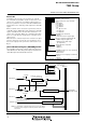
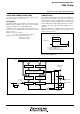
●Serial I/O2 Operating
The serial I/O2 counter is initialized to “7” by writing to the serial
I/O2 register.
After writing, whenever a synchronous clock changes from “H” to
“L”, data is output from the SOUT2 pin. Moreover, whenever a syn-
chronous clock changes from “L” to “H”, data is taken in from the
SIN2 pin, and 1 bit shift of the serial I/O2 register is carried out si-
multaneously.
When the internal clock is selected as a synchronous clock, it is
as follows if a synchronous clock is counted 8 times.
•Serial I/O2 counter = “0”
•Synchronous clock stops in “H” state
•Serial I/O2 interrupt request bit = “1”
The SOUT2 pin is in a high impedance state after transfer is com-
pleted.
When the external clock is selected as a synchronous clock, if a
synchronous clock is counted 8 times, the serial I/O2 interrupt re-
quest bit is set to “1”, and the SOUT2 pin holds the output level of
D7. However, if a synchronous clock continues being input, the
shift of the serial I/O2 register is continued and transmission data
continues being output from the SOUT2 pin.