
Specifications

SINGLE-CHIP 8-BIT CMOS MICROCOMPUTER
MITSUBISHI MICROCOMPUTERS
7560 Group
36
Serial I/O2
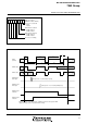
Serial I/O2 can be used only for clock synchronous serial I/O.
For serial I/O2, the transmitter and the receiver must use the
same clock as a synchronous clock. When an internal clock is se-
lected as a synchronous clock, the serial I/O2 is initialized and,
transmit and receive is started by a write signal to the serial I/O2
register.
When an external clock is selected as an synchronous clock, the
serial I/O2 counter is initialized by a write signal to the serial I/O2
register, serial I/O2 becomes the state where transmission or re-
ception can be performed. Write to the serial I/O2 register while
SCLK21 is “H” state when an external clock is selected as an syn-
chronous clock.
Either P62/SCLK21 or P63/SCLK22 pin can be selected as an output
pin of the synchronous clock. In this case, the pin that is not se-
lected as an output pin of the synchronous clock functions as a I/
O port.
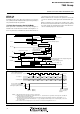
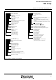
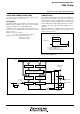
[Serial I/O2 Control Register (SIO2CON)] 001D16
The serial I/O2 control register contains eight control bits for the
serial I/O2 functions. After setting to this register, write data to the
serial I/O2 register and start transmit and receive.
Fig. 33 Structure of serial I/O2 control register
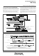
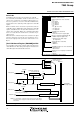
Fig. 34 Block diagram of serial I/O2 function
S
e
r
i
a
l
I
/
O
2
c
o
n
t
r
o
l
r
e
g
i
s
t
e
r
(
S
I
O
2
C
O
N
:
a
d
d
r
e
s
s
0
0
1
D
1
6
)
b7
Internal synchronous clock select bits
0 0 0: f(X
IN
)/8
0 0 1: f(X
IN
)/16
0 1 0: f(X
IN
)/32
0 1 1: f(X
IN
)/64
1 0 0:
1 0 1:
1 1 0: f(X
IN
)/128
1 1 1: f(X
IN
)/256
Serial I/O2 port selection bit
0: I/O port
1: S
OUT2
,S
CLK21
/S
CLK22
signal output
P6
1
/S
OUT2
P-channel output disable bit
0: CMOS output (in output mode)
1: N-channel open-drain output
(in output mode)
Transfer direction selection bit
0: LSB first
1: MSB first
Serial I/O2 synchronous clock selection bit
0: External clock
1: Internal clock
Synchronous clock output pin selection bit
0: S
CLK21
1: S
CLK22
b
0
b2 b1 b0
D
o
n
o
t
s
e
l
e
c
t
XI
N
“
1
”
“
0
”
“
0
”
“
1
”
“
0
”
“
1
”
SC
L
K
2
(
N
o
t
e
)
1
/
8
1
/
1
6
1
/
3
2
1
/
6
4
1
/
1
2
8
1
/
2
5
6
D
a
t
a
b
u
s
S
e
r
i
a
l
I
/
O
2
i
n
t
e
r
r
u
p
t
r
e
q
u
e
s
t
S
e
r
i
a
l
I
/
O
2
p
o
r
t
s
e
l
e
c
t
i
o
n
b
i
t
S
e
r
i
a
l
I
/
O
2
c
o
u
n
t
e
r
(
3
)
S
e
r
i
a
l
I
/
O
2
r
e
g
i
s
t
e
r
(
8
)
S
y
n
c
h
r
o
n
o
u
s
c
i
r
c
u
i
t
S
e
r
i
a
l
I
/
O
2
s
y
n
c
h
r
o
n
o
u
s
c
l
o
c
k
s
e
l
e
c
t
i
o
n
b
i
t
E
x
t
e
r
n
a
l
c
l
o
c
k
I
n
t
e
r
n
a
l
s
y
n
c
h
r
o
n
o
u
s
c
l
o
c
k
s
e
l
e
c
t
b
i
t
s
D
i
v
i
d
e
r
P
63
l
a
t
c
h
P
63/
SC
L
K
2
2
P
62/
SC
L
K
2
1
P
61/
SO
U
T
2
P
60/
SI
N
2
P
62
l
a
t
c
h
P
6
1
l
a
t
c
h
(
N
o
t
e
)
N
o
t
e
:
I
t
i
s
s
e
l
e
c
t
e
d
b
y
t
h
e
s
e
r
i
a
l
I
/
O
2
s
y
n
c
h
r
o
n
o
u
s
c
l
o
c
k
s
e
l
e
c
t
i
o
n
b
i
t
,
t
h
e
s
y
n
c
h
r
o
n
o
u
s
c
l
o
c
k
o
u
t
p
u
t
p
i
n
s
e
l
e
c
t
i
o
n
b
i
t
,
a
n
d
t
h
e
s
e
r
i
a
l
I
/
O
2
p
o
r
t
s
e
l
e
c
t
i
o
n
b
i
t
.