
Specifications

SINGLE-CHIP 8-BIT CMOS MICROCOMPUTER
MITSUBISHI MICROCOMPUTERS
7560 Group
20
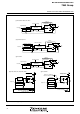
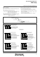
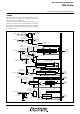
Fig. 16 Port block diagram (1)
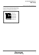
(5) Port P4
4
(
4
)
P
o
r
t
s
P
1
6
,
P
1
7
,
P
2
,
P
4
1
,
P
4
2
Pull-up control
V
L
1
/
V
S
S
V
L2
/V
L3
/V
CC
V
L1
/V
SS
V
L
2
/
V
L
3
/
V
C
C
V
L1
/V
SS
V
L
2
/
V
L
3
/
V
C
C
(
1
)
P
o
r
t
s
P
0
1
–
P
0
7
,
P
1
1
–
P
1
5
D
a
t
a
b
u
s
P
o
r
t
l
a
t
c
h
I
n
t
e
r
f
a
c
e
l
o
g
i
c
l
e
v
e
l
s
h
i
f
t
c
i
r
c
u
i
t
P
u
l
l
-
u
p
P
o
r
t
S
e
g
m
e
n
t
S
e
g
m
e
n
t
/
P
o
r
t
L
C
D
d
r
i
v
e
t
i
m
i
n
g
S
e
g
m
e
n
t
o
u
t
p
u
t
e
n
a
b
l
e
b
i
t
S
e
g
m
e
n
t
d
a
t
a
Port direction register
P
o
r
t
d
i
r
e
c
t
i
o
n
r
e
g
i
s
t
e
r
(
2
)
P
o
r
t
s
P
0
0
,
P
1
0
D
a
t
a
b
u
sP
o
r
t
l
a
t
c
h
Interface logic level
shift circuit
Port
S
e
g
m
e
n
t
Segment/Port
LCD drive timing
S
e
g
m
e
n
t
d
a
t
a
Port direction register
D
i
r
e
c
t
i
o
n
r
e
g
i
s
t
e
r
Pull-up
D
a
t
a
b
u
s
Port latch
I
n
t
e
r
f
a
c
e
l
o
g
i
c
l
e
v
e
l
s
h
i
f
t
c
i
r
c
u
i
t
P
o
r
t
S
e
g
m
e
n
t
Segment/Port
LCD drive timing
Segment data
P
o
r
t
P
3
ou
t
p
u
t
c
o
n
t
r
o
l
b
i
t
Pull-up
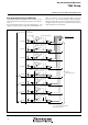
(
3
)
P
o
r
t
P
3
D
a
t
a
b
u
s
Port latch
D
i
r
e
c
t
i
o
n
r
e
g
i
s
t
e
r
Key input interrupt input
INT
1
, INT
2
interrupt input
E
x
c
e
p
t
P
1
6
,
P
1
7
P
u
l
l
-
u
p
c
o
n
t
r
o
l
Data bus
Port latch
D
i
r
e
c
t
i
o
n
r
e
g
i
s
t
e
r
S
e
r
i
a
l
I
/
O
1
e
n
a
b
l
e
b
i
t
S
e
r
i
a
l
I
/
O
1
i
n
p
u
t
R
e
c
e
i
v
e
e
n
a
b
l
e
b
i
t
S
e
g
m
e
n
t
o
u
t
p
u
t
e
n
a
b
l
e
b
i
t
S
e
g
m
e
n
t
o
u
t
p
u
t
e
n
a
b
l
e
b
i
t
Port P3 output
control bit