
Specifications

SINGLE-CHIP 8-BIT CMOS MICROCOMPUTER
MITSUBISHI MICROCOMPUTERS
7560 Group
19
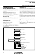
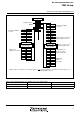
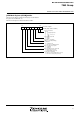
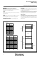
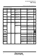
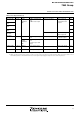
Pin Name I/O Format Non-Port Function Related SFRS
Diagram No.
Input/Output
Notes 1: How to use double-function ports as function I/O pins, refer to the applicable sections.
2: Make sure that the input level at each pin is either 0 V or V
CC before execution of the STP instruction. When an electric potential is at an
intermediate potential, a current will flow from V
CC to VSS through the input-stage gate and power source current may increase.
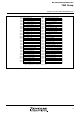
Table 9 List of I/O port function (2)
P60/SIN2/AN0
P61/SOUT2/
AN1
P62/SCLK21/
AN2
P63/SCLK22 /
AN3
P64/AN4–
P67/AN7
P70/INT0
P71–P77
COM0–COM3
SEG0–SEG17
Port P6
Port P7
Common
Segment
Input/
output,
individual
bits
Input
Input/
output,
individual
bits
Output
Output
CMOS compatible input
level
CMOS 3-state output
CMOS compatible input
level
CMOS compatible input
level
N-channel open-drain
output
LCD common output
LCD segment output
A-D converter input
Serial I/O2 I/O
A-D converter input
INT0 interrupt input
PULL register B
A-D control register
Serial I/O2 control
register
A-D control register
PULL register B
Interrupt edge
selection register
(17)
(18)
(19)
(20)
(16)
(23)
(13)
(21)
(22)
LCD mode register