
Specifications

SINGLE-CHIP 8-BIT CMOS MICROCOMPUTER
MITSUBISHI MICROCOMPUTERS
7560 Group
17
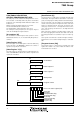
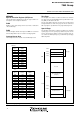
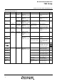
Fig. 15 Structure of PULL register A and PULL register B
Pull-up Control
By setting the PULL register A (address 001616) or the PULL reg-
ister B (address 001716), ports P0 to P2, P4 to P6 can control
pull-up with a program.
However, the contents of PULL register A and PULL register B do
not affect ports set to output mode and the ports are no pulled up.
The PULL register A setting is invalid for pins selecting segment
output with the segment output enable register and the pins are
not pulled up.
P
00,
P
01 pu
ll
-up contro
l
bi
t
P0
2, P03 pull-up control bit
P0
4–P07 pull-up control bit
P1
0–P13 pull-up control bit
P1
4, P15 pull-up control bit
P1
6, P17 pull-up control bit
P2
0–P23 pull-up control bit
P2
4–P27 pull-up control bit
P
U
L
L
r
e
g
i
s
t
e
r
A
(
P
U
L
L
A
:
a
d
d
r
e
s
s
0
0
1
61
6)
b
7
b
0
P
41–
P
43 pu
ll
-up contro
l
bi
t
P4
4–P47 pull-up control bit
P5
0–P53 pull-up control bit
P5
4–P57 pull-up control bit
P6
0–P63 pull-up control bit
P6
4–P67 pull-up control bit
Not used “0” at reading)
0
:
D
i
s
a
b
l
e
1
:
E
n
a
b
l
e
P
U
L
L
r
e
g
i
s
t
e
r
B
(
P
U
L
L
B
:
a
d
d
r
e
s
s
0
0
1
71
6)
b
7
b
0
N
ote:
Th
e contents o
f
PULL
reg
i
ster
A
an
d
PULL
reg
i
ster
B
do not affect ports set to output mode.