
Specifications

SINGLE-CHIP 8-BIT CMOS MICROCOMPUTER
MITSUBISHI MICROCOMPUTERS
7560 Group
12
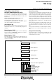
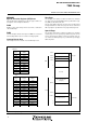
[Processor status register (PS)]
The processor status register is an 8-bit register consisting of 5
flags which indicate the status of the processor after an arithmetic
operation and 3 flags which decide MCU operation. Branch opera-
tions can be performed by testing the Carry (C) flag , Zero (Z) flag,
Overflow (V) flag, or the Negative (N) flag. In decimal mode, the Z,
V, N flags are not valid.
• Bit 0: Carry flag (C)
The C flag contains a carry or borrow generated by the arith-
metic logic unit (ALU) immediately after an arithmetic operation.
It can also be changed by a shift or rotate instruction.
• Bit 1: Zero flag (Z)
The Z flag is set to “1” if the result of an immediate arithmetic op-
eration or a data transfer is “0”, and set to “0” if the result is
anything other than “0”.
• Bit 2: Interrupt disable flag (I)
The I flag disables all interrupts except for the interrupt gener-
ated by the BRK instruction.
Interrupts are disabled when the I flag is “1”.
• Bit 3: Decimal mode flag (D)
The D flag determines whether additions and subtractions are
executed in binary or decimal. Binary arithmetic is executed
when this flag is “0”; decimal arithmetic is executed when it is
“1”.
Decimal correction is automatic in decimal mode. Only the ADC
and SBC instructions can be used for decimal arithmetic.
• Bit 4: Break flag (B)
The B flag is used to indicate that the current interrupt was gen-
erated by the BRK instruction. When the BRK instruction is
generated, the B flag is set to “1” automatically. When the other
interrupts are generated, the B flag is set to “0”, and the proces-
sor status register is pushed onto the stack.
• Bit 5: Index X mode flag (T)
When the T flag is “0”, arithmetic operations are performed be-
tween accumulator and memory. When the T flag is “1”, direct
arithmetic operations and direct data transfers are enabled be-
tween memory locations.
• Bit 6: Overflow flag (V)
The V flag is used during the addition or subtraction of one byte
of signed data. It is set to “1” if the result exceeds +127 to -128.
When the BIT instruction is executed, bit 6 of the memory loca-
tion operated on by the BIT instruction is stored in the V flag.
• Bit 7: Negative flag (N)
The N flag is set to “1” if the result of an arithmetic operation or
data transfer is negative. When the BIT instruction is executed,
bit 7 of the memory location operated on by the BIT instruction is
stored in the negative flag.
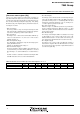
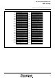
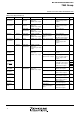
Table 7 Instructions to set each bit of processor status register to “0” or “1”
Instruction setting to “1”
Instruction setting to “0”
C flag
SEC
CLC
Z flag
–
–
I flag
SEI
CLI
D flag
SED
CLD
B flag
–
–
T flag
SET
CLT
V flag
–
CLV
N flag
–
–