PCA4738F-42A PCA4738L-64A PCA4738G-80A PCA4738H-100A PCA4738L-100A PCA4738S-42A PCA4738F-64A PCA4738S-64A PCA4738H-80A PCA4738F-80A PCA4738L-80A PCA4738G-100A PCA4738F-100A PCA4738L-160A PCA4738F-176A PROM Programming Adapters for 38000 Series User's Manual Rev. 1.
* TR4943, R4945 and R4945A are trademarks of Advantest Corporation. Keep safety first in your circuit designs! • Renesas Technology Corporation and Renesas Solutions Corporation put the maximum effort into making semiconductor products better and more reliable, but there is always the possibility that trouble may occur with them. Trouble with semiconductors may lead to personal injury, fire or property damage.
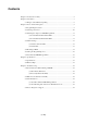
Contents Chapter 1. Precautions for Safety ........................................................................................... 5 Chapter 2. Introduction ........................................................................................................... 7 2.1 Things to Check When Unpacking ....................................................................... 8 Chapter 3. How to Write the Program .................................................................................... 9 3.
MEMO ( 4 / 26 )
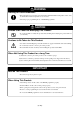
Chapter 1. Precautions for Safety Either in this user's manual or on the product, several icons are used to insure proper handling of this product and also to prevent injuries to you or other persons, or damage to your properties. This chapter describes precautions which should be taken in order to use this product safely and properly. Be sure to read this chapter before using this product.
WARNING Warning for Use Environment: • This equipment is to be used in an environment with a maximum ambient temperature of 35˚C. Care should be taken that this temperature is not exceeded. • Select the proper programming mode of the PROM programmer. CAUTION Caution to Be Taken for Modifying This Product: • Do not disassemble or modify this product. Disassembling and modifying the product will void your warranty. Cautions to Be Taken for This Product: • Use caution when handling this product.
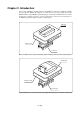
Chapter 2. Introduction This product is a PROM programming adapter for the 38000 Series of Renesas 8-bit MCUs (available for some 740 Series MCUs). The adapter is a tool that can be used to write programs into internal PROM of MCUs using a PROM programming adapter commercially available. This user's manual describes the specifications and how to use the product. Figures 2.1 and 2.2 show external views of the PROM programming adapters and their constituent parts.
2.1 Things to Check When Unpacking This product package consists of the items listed in Table 2.1. Check to see that it contains all of the items when unpacking. Table 2.
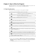
Chapter 3. How to Write the Program This chapter describes how to write programs with a PROM programmer. For the operation of the PROM programmer, refer to the user's manual of the PROM programmer. 3.1 Programming Procedures Follow these procedures (1) through (9) to write programs into the MCU. (1) Read the program into the PROM programmer. (Offset: 800016)*1 *1 Offset address not required when writing in M5M27C101 mode. (2) Select the connector corresponding to the MCU. (See Section 3.
3.2 Selecting a Connector Select the connector depending on the type of the MCU as described in Table 3.1 and Figure 3.1 below. Table 3.
3.3 Attaching the Adapter to a PROM Programmer (1) For the PCA4738D and PCA7402D As shown in Figure 3.2, attach the pin No. 1 of the connector of the PROM programmer (standardpitch 28-pin pin-header mounted) to the No. 1 pin of the IC socket of the PROM programmer. Be careful when attaching to the PROM programmer because an incorrect insertion can cause fatal damage to the MCU.
3.4 Switch Settings (1) Switches SW1 and SW2 • For PCA4738S-42A and PCA4738F-42A Set the switches SW1 and SW2 according to the output format of the MCU ports. The examples of switch settings are shown in Tables 3.2 and 3.5 and Figure 3.4. Table 3.
Table 3.
3.5 Mounting an MCU As shown in Figures 3.5 and 3.6, insert the No. 1 pin of an MCU into the No. 1 pin of the IC socket. Be careful when inserting the MCU because an incorrect insertion can cause fatal damage to the MCU. Top view PCA4738X-XXA REV. A IC1 1 No. 1 pin of MCU X1 IC socket JAPAN Figure 3.5 Mounting an MCU (adapters with DIP type IC socket) Top view PCA4738X-XXA REV. A J1 J2 IC1 1 1 IC socket RA2 No.
CAUTION Caution to Be Taken for SOP Version IC Socket: • SOP version IC sockets (mounted on the PCA4738F-42A) have a sliding bar in the middle of the board. Be sure to keep the bar to the side of the diagonally shaded area imprinted on the board (factory-setting). An improper setting will cause fatal damage to the MCU due to faulty connections. Top view PCA4738x-xxA REV.A J1 J2 IC1 42 22 IC socket Sliding bar No.
3.6 Setting the Programming Area To write the program into an MCU, be sure to set the programming area. And also, specify its device of the PROM programmer. The lists of programming areas and device are shown in Tables 3.6 to 3.9. Make note of the fact that the MCU whose ROM is 32 KB or less has two devices applicable. For the MCUs not listed in Tables 3.6 to 3.9, refer to each MCU's user's manual. Table 3.
Table 3.
Table 3.
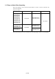
Chapter 4. Specifications 4.1 Specifications Table 4.1 lists common specifications of the programming adapters, and Tables 4.2 and 4.3 list individual specifications of each programming adapter. Table 4.
Table 4.3 Individual specifications (2/2) Product name Description Item MCU PCA4738F-80A IC socket MCU PCA4738L-80A IC socket MCU PCA4738H-80A IC socket MCU PCA4738G-80A IC socket MCU PCA4738F-100A IC socket MCU PCA4738L-100A IC socket MCU PCA4738G-100A IC socket MCU PCA4738H-100A IC socket MCU PCA4738L-160A IC socket MCU PCA4738F-176A IC socket 38000 Series QFP package (80P6N-A) 3806, 3807, 3817, 3820, 3822 Group 80-pin FP package IC51-0804-819-6 (made by Yamaichi Electronics Co., Ltd.
4.2 Memory Maps Memory maps of the MCU and PROM programmers are shown in Figure 4.1 (M5M27C256A mode) and Figure 4.2 (M5M27C101 mode).
00000h 00000h 0YY00h 0YY7Fh 0YY80h Unused area Reserved ROM area 0ZZ7Fh 0ZZ80h Programming area Internal ROM area 0FFFDh 0FFFEh 0FFFDh 0FFFEh Reserved ROM area 0FFFFh MCU Unused area 1FFFFh PROM programmer (M5M27C101 mode) ROM size (Bytes) E1: Address YY Address ZZ F0 F0 4,096 E2: 8,192 E0 E0 E3: 12,288 D0 D0 E4: 16,384 C0 C0 E5: 20,480 B0 B0 E6: 24,576 A0 A0 E7: 28,672 90 90 E8: 32,768 80 80 E9: 36,864 70 70 EA: 40,960 60 60 EB: 45,056 50 50 EC: 49
Chapter 5. Troubleshooting Be sure to check the following before seeking technical support. 5.
5.2 MCU Does Not Function Normally In the case that the program operates normally on the emulator, but when the MCU that has normally been written is attached the same program does not function normally: (1) Is the offset address specified correctly when copying data into the PROM programmer? (2) In the emulator, NOPs are often inserted in the area where the program has not been read, therefore the program happens to appear functioning normally even though it may have gone wild. Check your program again.
PROM Programming Adapter for 38000 Series User's Manual Rev. 1.