
User`s manual


7.Appendix
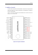
7.1.9. I/O Port Setting
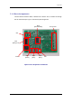
(1)LED
The LED2 to 4 are connected to the programmable I/O port. They can be lighted by
a program.
Table 7-3 LED Pin
LED PORT Pin No
LED2 P30 19
LED3 P31 20
LED4 P32 21
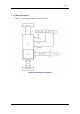
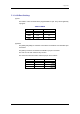
(2)Switch
The [SW2] and [SW3] are switches connected to the P34/INT1 and P37/INT0 pins
in the MCU.
The [SW1] is a switch connected to the RESET input pin in the MCU.
The user can use each switch for any function.
The connection with each switch and the input pin are as follows.
SW Input Pin Remarks
SW1 RESET
SW2 P34/INT1
SW3 P37/INT0
60