
User`s manual
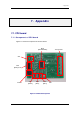

7.Appendix
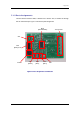
7.1.4. Connector Specification
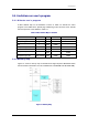
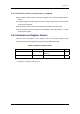
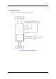
Figure 7-2 shows the pin assignment of CN2.
1
10
9
8
7
6
5
4
3
2
P4_1
P4_0
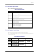
PortPin No
Signal
TxD
GND
RxD
Vcc
10-Pin Connector
Connector Type
HIF3FC-10PA-2.54DSA
10-Pin Connector assign
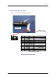
P4_2
P4_3
RESET
SCLK
BUSY
1
10
9
8
7
6
5
4
3
2
Output
Output
Input
Not Used
Input
KD connector
Pin No.1
Not Used
Not Used
Figure 7-2 Pin Assignment of CN2
55