
User`s manual

5.Limitations
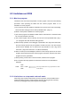
5.4. Limitations on user's program
5.4.1. Allocate user's program
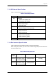
A MCU address map for the StarterKit is shown in Table 5-2. Allocate the user's
program to the RAM2 area. Special page addressing mode cannot be used. Allocate
the interrupt vector to the address in Table 5-1.
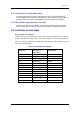
Table 5-2 MCU Address Map for StaterKit
Name Address Memory Enabled/Disabled Limitation
SFR Area (Zero Page)
0000
16
to 003F
16
RAM Enabled
NOTE) Refer to
Table 5-3
.
RAM1 (Zero Page)
0040
16
to 00FF
16
RAM Enabled -
RAM1
0100
16
to 013F
16
RAM Enabled -
RAM2 (Monitor Program Area)
2000
16
to 207F
16
RAM Disabled Disabled
RAM2
2080
16
to 3FDB
16
RAM Enabled -
RAM2 (User Interrupt Vector Area)
3FDC
16
to 3FFD
16
RAM
Enabled
BRK instruction interrupt
disabled
ROM (Monitor Program Area)
E000
16
to FFFD
16
ROM Disabled Disabled
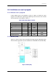
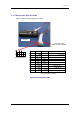
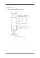
5.4.2. Memory map
Figure 5-1 shows a memory map of Renesas 8-bit single-chip MCU M37594G2 which
the CPU board incorporates. The user enabled area is (SFR RAM1 256 B, RAM2 8KB).
Figure 5-1 Memory Map
50