REJ10B0239-0140 M3S-UFLA32R User’s Manual UART Flash Memory Programming Utility All information contained in these materials, including products and product specifications, represents information on the product at the time of publication and is subject to change by Renesas Technology Corp. without notice. Please review the latest information published by Renesas Technology Corp. through various means, including the Renesas Technology Corp. website (http://www.renesas.com). Rev.1.40 Revision Date: Mar.
Notes regarding these materials 1. This document is provided for reference purposes only so that Renesas customers may select the appropriate Renesas products for their use. Renesas neither makes warranties or representations with respect to the accuracy or completeness of the information contained in this document nor grants any license to any intellectual property rights or any other rights of Renesas or any third party with respect to the information in this document. 2.
Precautions on Using The Product Described Herein 1. The product described herein should be used in combination with the parts included with the starter kit. If the product is operated in combination with any other item, its operation cannot be guaranteed. Nor will requests for help or suggestion be answered. 2. The product described herein was prepared for program development or evaluation purposes. The product cannot be used for the mass production. 3.
Contents 1. Overview .......................................................................................................................1 2. System Configuration ....................................................................................................1 2.1 2.2 2.3 2.4 3. Outline of the M3S-UFLA32R................................................................................................................ 1 Communication Cable (M3A-2145G50) .............................................
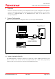
M3S-UFLA32R UART Flash Memory Programming Utility 1. Overview This user’s manual is intended to provide explanations about system configuration and operation method of the UART Flash Memory Programming Utility M3S-UFLA32R Ver.1.40 (hereinafter referred to as M3S-UFLA32R) for the M32R/ECU Series (Refer to the Table 2.3.1 for corresponding MCU). 2. System Configuration Figure 2.1.
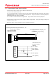
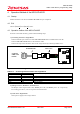
M3S-UFLA32R UART Flash Memory Programming Utility 2.2 Communication Cable (M3A-2145G50) Communication cable consists of two different cables below. •Interface Cable (M3A-2145G02) It is a conversion cable to connect to the test pins on the target when the connection cable for the MF-TEN-NINE can not be mounted on the target board. Figure 2.2.1 shows connecting diagram. •MF-TEN-NINE Cable (M3A-0652CBL) It is a cable to connect host PC to target board. Figure 2.2.2 shows connecting diagram.
RJJ99J0021-0100 M3S-UFLA32R UART Flash Memory Programming Utility Figure 2.2.2 MF-TEN-NINE Cable Connecting Diagram REJ10B0239-0140/Rev.1.40 Mar.
M3S-UFLA32R UART Flash Memory Programming Utility Table 2.2.1 Usage Specification Rated Value MIN MAX Unit RS-232C Communication Rate Consumption Current 3.0 4.5 9600 - 3.6 5.5 115200 60 V V bps mA Operating Ambient Temperature 5 35 °C Storage Ambient Temperature 0 60 °C Parameter DC Power Supply 2.
M3S-UFLA32R UART Flash Memory Programming Utility 3. Installation of the M3S-UFLA32R 3.1 Installation of the M3S-UFLA32R To install the M3S-UFLA32R, perform the following steps. 1) Execute Setup.exe in "¥Eng¥Tool¥Ufla32r¥W95E" folder contained in the provided CD. (Note1) 2) Continue installation by following the instruction of the installation window. 3) Installation is completed when Setup Complete dialog appears.
M3S-UFLA32R UART Flash Memory Programming Utility 4. Operation Method of the M3S-UFLA32R 4.1 Startup Double-click the icon after the M3S-UFLA32R setup is completed. 4.2 Exit Choose [Exit(X)] from [File(F)] menu. 4.3 Operation Outline of the M3S-UFLA32R To write to the flash memory, perform the following steps. 1) Connecting Host PC to Target Board •Connect D-Sub 9 pin connector of the MF-TEN-NINE cable to COM1 of the host PC. •Connect MF-TEN-NINE cable to the interface cable.
M3S-UFLA32R UART Flash Memory Programming Utility 4) Reset the Target MCU Reset the target MCU by pressing the reset switch on the target board. 5) Starting the M3S-UFLA32R Start the M3S-UFLA32R. 6) Execution of Writing to the Flash Memory by the M3S-UFLA32R Operate the M3S-UFLA32R and perform writing to the flash memory. For detail about operation method, refer to "5. Function Description of the M3S-UFLA32R.
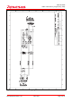
M3S-UFLA32R UART Flash Memory Programming Utility 5. Function Description of the M3S-UFLA32R 5.1 Function List Table 5.1 lists functions of the M3S-UFLA32R. Choose each function from menu or click a button for execution. Table 5.1 Function List File Menu Load Display Device Exit Lock Bit Information Program Erase Block Erase Lock Bit / Set Button Refer Program Erase - Lock Bit / Enable Lock Bit / Disable Blank Check Verify Check Blank Check Verify Check Batch processing / E.B.P.V.
M3S-UFLA32R UART Flash Memory Programming Utility 5.2 Program Data (Motorola S-format file) Selection (1) Choose [Load(L)] from [File(F)] menu or click [Refer] button. Figure 5.2.1 Program Data Selection (2) When “Open File” dialog opens, choose a program data file (Motorola S-format file) and then click [Open(O)] button. Note: As a file format, the M3S-UFLA32R supports Motorola S-format only. Figure 5.2.2 Open File Dialog REJ10B0239-0140/Rev.1.40 Mar.
M3S-UFLA32R UART Flash Memory Programming Utility (3) Choose a file to display the dialog that shows execution process, and then read program data file into the internal buffer. After completing read, the dialog is closed and file name is displayed in "File Name:" box. Figure 5.2.3 Result of Choosing Program Data 5.3 Exit the Application (1) Choose [Exit(X)] from [File(F)] menu to exit the program. Also, it is able to exit the program by pushing [Alt + F4] keys or clicking the close button. Figure 5.
M3S-UFLA32R UART Flash Memory Programming Utility 5.4 Lock Bit Information (1) Choose [Lock Bit Information (L)] from [Display(V)] menu to display the dialog that shows execution process, and then read lock bit. After completing read of lock bit, the dialog is closed and "Lock Bit Status Display" dialog is displayed. Figure 5.4.1 Lock Bit Information (2) Click [Cancel] while reading out lock bit status to close the dialog that shows execution process. Figure 5.4.
M3S-UFLA32R UART Flash Memory Programming Utility (3) In [Lock Bit Status Display] dialog, the lock bit statuses of all blocks of currently selected MCU are displayed. Click [OK] to close "Lock Bit Status Display" dialog. Figure 5.4.3 Lock Bit Status Display Dialog REJ10B0239-0140/Rev.1.40 Mar.
M3S-UFLA32R UART Flash Memory Programming Utility 5.5 Program (1) Choose [Program(P)] from [Device(D)] menu or click [Program] button to display the dialog that shows execution process, and then write program data stored in the internal buffer to the flash memory. After completing write of program data, the dialog is closed and "Program …finish" dialog is displayed. Figure 5.5.1 Program (2) Click [OK] in the "Program…finish" dialog to close the dialog Figure 5.5.
M3S-UFLA32R UART Flash Memory Programming Utility 5.6 Erase (1) Choose [Erase(E)] from [Device(D)] menu or click [Erase] button to display the dialog that shows execution process, and then erase the flash memory. After completing the flash memory erasing, the dialog is closed and "Erase …finish" dialog is displayed. Figure 5.6.1 Erase (2) Click [OK] in the "Erase…finish" dialog to close the dialog. Figure 5.6.2 Erase Finish Dialog REJ10B0239-0140/Rev.1.40 Mar.
M3S-UFLA32R UART Flash Memory Programming Utility 5.7 Block Erase (1) Choose [Block Erase(L)] from [Device(D)] menu to display "Block Erase" dialog. Figure 5.7.1 Block Erase (2) In "Block Erase" dialog, all blocks of currently selected MCU are displayed. Click [Select All] to select all blocks. Click [Clear] button to clear all selected blocks. Select the blocks you wish to erase and click [OK] to close "Block Erase" dialog.
M3S-UFLA32R UART Flash Memory Programming Utility (3) Click [OK] in the "Block Erase…finish" dialog to close the dialog. Figure 5.7.3 Block Erase Finish Dialog REJ10B0239-0140/Rev.1.40 Mar.
M3S-UFLA32R UART Flash Memory Programming Utility 5.8 Lock Bit/Set (1) Choose [Lock Bit]-[Set(S)] from [Device(D)] menu to display the dialog that shows execution process, and then read out lock bit. After completing read of lock bit, the dialog is closed and "Lock Bit Set" dialog is displayed. Figure 5.8.1 Lock Bit Set Note: To clear lock bit, perform the following steps. 1. Execute [Lock Bit]-[Disable(D)] in [Device(D)] menu. 2. Execute [Erase(E)] or [Block Erase(L)] in [Device(D)] menu.
M3S-UFLA32R UART Flash Memory Programming Utility (2) In "Lock Bit Set" dialog, the blocks without setting of lock bit are displayed. Click [Select All] to select all blocks. Click [Clear] to clear all selected blocks. Select the blocks you wish to set lock bit to, and then click [OK] to close "Lock Bit Set" dialog. Subsequently, the dialog that shows execution process appears and the lock bit is set. After completing setting, the dialog is closed and "Lock Bit Set …finish" dialog is displayed.
M3S-UFLA32R UART Flash Memory Programming Utility 5.9 Lock Bit/Enable (1) Choose [Lock Bit]-[Enable(E)] from [Device(D)] menu to display the dialog that shows execution process, and then enable lock bit. After completing enabling lock bit, the dialog is closed and "Lock Bit Enable…finish" dialog is displayed. Note: It can not perform erase or write operation against the block with the lock bit that is enabled and set. Clear lock bit to perform erase or write operation.
M3S-UFLA32R UART Flash Memory Programming Utility 5.10 Lock Bit/Disable (1) Choose [Lock Bit]-[Disable(D)] from [Device(D)] menu to display the dialog that shows execution process, and then disable lock bit. After completing disabling lock bit, the dialog is closed and "Lock Bit Disable…finish" dialog is displayed. Figure 5.10.1 Lock Bit Disable (2) Click [OK] in the "Lock Bit Disable…finish" dialog to close the dialog. Figure 5.10.2 Lock Bit Disable Finish Dialog REJ10B0239-0140/Rev.1.40 Mar.
M3S-UFLA32R UART Flash Memory Programming Utility 5.11 Blank Check (1) Choose [Blank Check(B)] from [Device(D)] menu or click [Blank Check] button to display the dialog that shows execution process, and then perform blank check operation. After completing blank check, the dialog is closed and "Blank Check…finish" dialog is displayed. Figure 5.11.1 Blank Check (2) Click [OK] in the "Blank Check…finish" dialog to close the dialog. Figure 5.11.2 Blank Check Finish Dialog REJ10B0239-0140/Rev.1.40 Mar.
M3S-UFLA32R UART Flash Memory Programming Utility 5.12 Verify Check (1) Choose [Verify Check(V)] from [Device(D)] menu or click [Verify Check] button to display the dialog that shows execution process, and then perform verify check operation. After completing verify check, the dialog is closed and "Verify Check…finish" dialog is displayed.
M3S-UFLA32R UART Flash Memory Programming Utility 5.13 E.B.P.V. (Erase, Blank Check, Program, Verify Check) (1) Choose [Batch Processing]-[E.B.P.V.] from [Device(D)] menu or click [E.B.P.V.] button to consecutively execute "Erase," "Blank Check," "Program," and "Verify Check." Figure 5.13.1 E.B.P.V. 5.14 E.P. (Erase, Program) (1) Choose [Batch Processing]-[E.P.] from [Device(D)] menu or click [E.P.] button to consecutively execute "Erase" and "Program." Figure 5.14.1 E.P. REJ10B0239-0140/Rev.1.
M3S-UFLA32R UART Flash Memory Programming Utility 5.15 B.P.V. (Blank Check, Program, Verify Check) (1) Choose [Batch Processing]-[B.P.V.] from [Device(D)] menu or click [B.P.V.] button to consecutively execute "Blank Check," "Program," and "Verify Check." Figure 5.15.1 B.P.V. REJ10B0239-0140/Rev.1.40 Mar.
M3S-UFLA32R UART Flash Memory Programming Utility 5.16 Setting (1) Choose [Setting(S)] from [Others(O)] menu to display "Setup" dialog. Figure 5.16.1 Setting REJ10B0239-0140/Rev.1.40 Mar.
M3S-UFLA32R UART Flash Memory Programming Utility (2) In the "Setup" dialog, it is possible to choose MCU type, verify process, and write ID code into the ID code area. It is possible to choose MCU from "Mcu Type(M)" pull-down menu. It is possible to choose verify check process from "Verify process(V)." Choose [Sum check (high speed)] to compare the data in MCU to the check sum value of the program data file.
M3S-UFLA32R UART Flash Memory Programming Utility 5.17 ID Code Setting (1) Choose [ID Code Setting(I)] from [Others(O)] menu to display "ID code setting" dialog. Figure 5.17.1 ID Code Setting REJ10B0239-0140/Rev.1.40 Mar.
M3S-UFLA32R UART Flash Memory Programming Utility (2) In the "ID code setting" dialog, the ID code for verification is set. Table 5.17.1 shows function list of operable and not operable functions according with the verify result. Choose [Specify ID code by hexadecimal] to set the ID code by hexadecimal. Choose [Specify ID code by alphanumeric] to set the ID code by alphanumeric characters. Click [OK] to enable the setting, and then close the "ID code setting" dialog.
M3S-UFLA32R UART Flash Memory Programming Utility 5.18 Version Information (1) Choose [Version information (UFLA32R) (A)] from [Help(H)] menu to display "Version information (UFLA32R)" dialog. Figure 5.18.1 Version Information (2) In the "Version information (UFLA32R)" dialog, the M3S-UFLA32R version and Flash E/W Firmware version in the MCU are displayed. Click [OK] to close the dialog. Figure 5.18.2 Version Information (UFLA32R) Dialog REJ10B0239-0140/Rev.1.40 Mar.
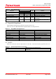
M3S-UFLA32R UART Flash Memory Programming Utility 6. Error Message List Table 6.1.1 lists error messages, causes, and approaches provided from the M3S-UFLA32R. Table 6.1.1 Error Message List 1 2 3 4 Error Message MCU information is incorrect. Please check whether the "UFLA32R.ini" file is installed correctly. Can not open COM1. Cause There is no INI file. Approach Reinstall the M3S-UFLA32R. Can not open COM1. Motorola file is not specified. Please specify Motorola file.
M3S-UFLA32R UART Flash Memory Programming Utility Revision History Description Summary Rev. Date 1.00 Jun 25, 2000 Page - 1.01 Dec 4, 2000 - 1.02 Jan 29, 2002 7 1.03 Feb 14, 2002 7 1.04 Mar 1, 2002 2 Changed output message from Japanese to English. Added references to 2) Connecting Host PC with Target System in Chapter 3. Changed product name from UFLA32 to M3A-UFLA32R. Changed the description of 2) Connecting Host PC with Target System in Chapter 3.
Uart Flash Memory Programming Utility User’s Manual M3S-UFLA32R Publication Date: 1st Edition, Jun., 2000 Rev.1.40, Mar. 06, 2007 Published by: Sales Strategic Planning Div. Renesas Technology Corp. 2007. Renesas Technology Corp., All rights reserved. Printed in Japan.
M3S-UFLA32R User’s Manual 2-6-2, Ote-machi, Chiyoda-ku, Tokyo, 100-0004, Japan