REJ11J0015-0101 SH7670 CPU Board M3A-HS71 32 Installation Manual Renesas 32-Bit RISC Microcomputers SuperHTM RISC engine Family/SH7670 Series Rev. 1.01 Issued: May 7.
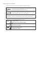
[Indication of Warnings and Cautions] The following explains the warnings and cautions indicated for the handling of the product. WANING If the product is improperly handled without regard for this indication, there will be a possibility of inflicting death or heavy wound on persons. CAUTION If the product is improperly handled without regard for this indication, there will be a possibility of inflicting an injury on persons or physical damage.
Important Before using this product, be sure to read the user’s manual (this user's manual) carefully. Keep this user’s manual, and refer to this when you have questions about this product. About this product: The term “this product” referred to here mean the product manufactured by Renesas Technology Corporation. It does not include the user systems and host machines of the customers.
Usage restrictions: This product has been developed as a means of supporting system development by users. Therefore, do not use it as a device used for equipment-embedded applications.
Table of Contents CHAPTER1 BEFORE USING THE SH7670 CPU BOARD ................................................................. 1-1 1.1 Overview ...................................................................................................................................................................... 1-2 1.2 Usage Precautions....................................................................................................................................................... 1-2 1.2.1 Symbols Used .
5.2.3 Activating the Command Line Window ............................................................................................................... 5-10 5.3 Adding/Modifying Hardware Setup Files .................................................................................................................... 5-10 5.3.1 Copying Hardware Setup Files ........................................................................................................................... 5-10 5.3.
*This page is blank* Rev. 1.
Chapter1Before Using the SH7670 CPU Board Chapter1 Before Using the SH7670 CPU Board 1-1
Before Using the SH7670 CPU Board 1 1.1 Overview 1.1 Overview The SH7670 CPU board(board type name: M3A-HS71) consists of the SH7670 CPU board and the sample software. This installation manual describes mainly how to set up the SH7670 CPU board hardware and software. For more information about SH7670 hardware and programming manual, refer to the manuals in CD-ROM included with this product.
Before Using the SH7670 CPU Board 1 1.2.1 Symbols Used CAUTION Regarding the reconstruction of this product: • Do not reconstruct this product. If the product has gotten out of order for reasons of disassembly or reconstruction, requests for repair may not be accepted. Regarding the handling of this product: z Handle this product with caution, not to let it drop or fall down or apply strong mechanical shock.
Before Using the SH7670 CPU Board 1 1.3 Procedure for Introducing This Product 1.3 Procedure for Introducing This Product In this manual, we follow the procedure outlined in Figure 1.3.1 to perform the installation. Figure 1.3.1 SH7670 CPU board Installation Procedure 1.
Before Using the SH7670 CPU Board 1 1.5 Items to Be Prepared by User 1.5 Items to Be Prepared by User The following lists the items that need to be prepared by users separately from this product. You need to prepare the following power supply separately from the product package in order to supply power to the SH7670 CPU board. Table 1.5.1 Items to Be Prepared by User (For SH7670 CPU board) No. 1 Item to Be Prepared by User Remark 1.
Before Using the SH7670 CPU Board 1 1.5 Items to Be Prepared by User *This page is blank* Rev. 1.
Chapter2Setting Up the Hardware Chapter2 Setting Up the Hardware 2-1
Setting Up the Hardware 2 2.1 Connections Between SH7670 CPU board and E10A-USB Emulator 2.1 Connections Between SH7670 CPU board and E10A-USB Emulator Figure 2.1.1 shows how SH7670 CPU board and E10A-USB emulator should be connected. Figure 2.1.1 System Connection of SH7670 CPU board and E10A-USB Emulator 2.2 SH7670 CPU board Switch Setting The following describes how to set the switches of SH7670 CPU board.
Setting Up the Hardware 2 2.2.1 SH7670 CPU board DIP Switch Setting 2.2.1 SH7670 CPU board DIP Switch Setting To use the SH7670 CPU board following the installation described here, be sure to set the DIP switch SW8 to its default settings as shown in Figure 2.2.1 and Table 2.2.1. ON SW8 Board edge Figure 2.2.1 DIP Switch Setting Table 2.2.1 Switch SW8 Functions Switch No.
Setting Up the Hardware 2 2.3 System Connections and Power-On Sequence 2.3 System Connections and Power-On Sequence Follow the same procedure when you check to see that the power for the host computer is turned off, or that the E10A-USB emulator is not connected to the host computer with USB cable. 1. 2. 3. 4. Connect the SH7670 CPU board and the E10A-USB emulator with the user interface cable. Plug the USB cable into the connector on the host side of the E10A-USB emulator.
Chapter3Setting Up the Software Chapter3 Setting Up the Software 3-1
Setting Up the Software 3 3.1 About the HEW 3.1 About the HEW HEW, or High-performance Embedded Workshop, is an integrated development environment with a graphical user interface designed to help users develop and debug the applications created in C/C++ and assembly languages for use in Renesas microcomputers. The SH7670 CPU board based software development is carried out by using the HEW.
Setting Up the Software 3 3.1 About the HEW (2) Figure 3.1.2 is displayed, and click “Next”. Figure 3.1.2 HEW Installation Procedure (2) Note: If you have already installed a HEW on your PC, you can select “Install a new High-performance Embedded Workshop” and install a new HEW in another directory on your PC. (3) Continue to install following the instructions in the installation window. (4) Next, install an Autoupdate Utility. Click “Next”. Figure 3.1.
Setting Up the Software 3 3.1 About the HEW (5) Continue to install following the instructions in the installation window. When entire installation is finished, the dialog shown in Figure 3.1.4 is displayed, click “Exit”. Figure 3.1.4 HEW Installation Procedure (5) Rev. 1.
Setting Up the Software 3 3.2.1 E10A-USB Software Installation Procedure 3.2 Setting Up the E10A-USB Emulator Software Next, the following explains how to set up the E10A-USB emulator software. 3.2.1 E10A-USB Software Installation Procedure (1) Execute “HewInstMan.exe” included in the E10A-USB emulator software CD-ROM. High-performance Embedded Workshop Install Manager is activated, and click “Installation”. Figure 3.2.
Setting Up the Software 3 3.2.1 E10A-USB Software Installation Procedure Note: If you have already installed a HEW on your PC, you can select “Install a new High-performance Embedded Workshop” and install a new HEW in another directory on your PC. (3) When the dialog box shown in Figure 3.2.3 is displayed, select “SuperH RISC engine Family SH-2A Device Group” and “SH7670”, then click “Next”. Figure 3.2.3 E10A-USB Software Installation Procedure (3) (4) Click “Next to start the installation.
Setting Up the Software 3 3.2.1 E10A-USB Software Installation Procedure (5) Next, install an Autoupdate Utility. Click “Next”. Figure 3.2.5 E10A-USB Software Installation Procedure (5) Note: When you have not selected “Autoupdate” on the Choice of an installation product, the above dialog is not displayed. (6) When the installation is complete, the dialog shown in Figure 3.2.6 is displayed. Click “Finish”. Figure 3.2.6 E10A-USB Software Installation Procedure (6) Rev. 1.
Setting Up the Software 3 3.2.1 E10A-USB Software Installation Procedure (7) When entire installation is finished, the dialog shown in Figure 3.2.7 is displayed, click “Exit”. Figure 3.2.7 E10A-USB Software Installation Procedure (7) Rev. 1.
Setting Up the Software 3 3.2.2 Setting Up the E10A-USB Emulator 3.2.2 Setting Up the E10A-USB Emulator (i) Setting Up New Firmware The following explains the case where you set up new firmware of the E10A-USB emulator. If your E10A-USB emulator already has the firmware suitable for the SH-2A group, skip this step and go to paragraph (ii) “Setting Up the E10A-USB Emulator Driver.” Firmware setup requires changing the DIP switch settings on the E10A-USB emulator main unit.
Setting Up the Software 3 3.2.2 Setting Up the E10A-USB Emulator (1) Open the slide switch cover on the E10A-USB emulator main unit, and check to see that the emulator setup switch (SW1) is set to the “1” side. (2) From [All Programs] on [Start menu], choose [Renesas High-performance Embedded Workshop] Æ [Setup Tool for E10A-USB Emulator] Æ [SH-2A Device Group]. An E10A-USB emulator setup tool will start up. (a) (b) (c) Figure3.2.
Setting Up the Software 3 3.2.2 Setting Up the E10A-USB Emulator Notes • If the versions shown in (b) and (c) are the same, you do not need to set up. If the version shown in (b) is “-.-.--.---” or older than the version in (c), you need to set up. • If the emulator connected to your system is not the E10A-USB emulator suitable for the SH7670, the error message shown below will be displayed, with the setup tool thereby terminated.
Setting Up the Software 3 3.2.2 Setting Up the E10A-USB Emulator (3) Press “Setup”(Figure3.2.9). The dialog box shown below will be displayed. Figure3.2.12 Setup Tool for SHxxxx E10A-USB Emulator Dialog Box (4) Set the emulator setup switch (SW1) to the “0” side, and temporarily remove the USB cable and plug it in back again. Then click “OK”. The system will start setting up the E10A-USB emulator firmware. Figure3.2.
Setting Up the Software 3 3.2.2 Setting Up the E10A-USB Emulator (6) After the E10A-USB emulator setup is completed, the message shown below will be displayed. Set the emulator setup switch (SW1) to the “1” side, and temporarily remove the USB cable and plug it in back again. Then click “OK”. Figure3.2.15 Setup Tool for SH-2A E10A-USB Emulator Dialog Box Note: Always make sure the emulator setup switch (SW1) remains in the “1” side unless the setup tool is used.
Setting Up the Software 3 3.2.2 Setting Up the E10A-USB Emulator (ii) Setting Up the E10A-USB Emulator Driver The following shows how to set up the E10A-USB emulator driver. The setup procedure here is explained for the Windows XP case. Note: The dialog boxes shown here are displayed when you set up the E10A-USB emulator driver for the first time or when you’ve changed the USB port on the host computer side and connected the emulator to that port for the first time.
Setting Up the Software 3 3.2.2 Setting Up the E10A-USB Emulator (3) Search the CD-ROM for drivers and select” :¥driver¥usb¥xp¥elusb.inf“ and then click “Next”. The ‘xp’ in the underlined part (in the setup here, Windows XP) indicates the OS version. Figure3.2.19 New Hardware Detection Wizard Start (3) Note: If [Hardware installation] dialog box, which says the software has not passed Windows Logo.. is displayed, just click “Continue Anyway”.
Setting Up the Software 3 3.2.2 Setting Up the E10A-USB Emulator (5) Activate Device Manager to confirm whether the USB controller driver has been installed. Choose [Control Panel] from [Start menu] and double-click [System] icon. In [System Properties] dialog box, click the [Hardware] tab and then [Device Manager]. Figure3.2.21 Confirming in the Device Manager Window Rev. 1.
Setting Up the Software 3 3.2.2 Setting Up the E10A-USB Emulator *This page is blank* Rev. 1.
Chapter4Running the Software Chapter4 Running the Software 4-1
Running the Software 4 4.1 Running the Software 4.1 Running the Software This product comes with sample software for verifying the hardware operation as technical reference material for software development. The following describes the necessary steps to be followed before the load module of the sample software can be downloaded. Note: To execute the sample software, the DIP switch (SW8) on the SH7670 CPU board should be set as the initial setting. 4.1.
Running the Software 4 4.1.2 SH7670 CPU board and E10A-USB Startup Procedure (HEW Startup) (5) The [Open Workspace] dialog box shown below is displayed. In this dialog box, specify the directory indicated below. "C:¥WorkSpace¥Sample_software¥SH7670_sample" (6) After specifying the directory, select the file indicated below and click “Select”. Figure 4.1.
Running the Software 4 4.1.2 SH7670 CPU board and E10A-USB Startup Procedure (HEW Startup) Note: For the first time only, a message “Please choose driver” is displayed. Click “OK” to display the Driver Details, and select “Renesas E-Series Driver” for the Driver. Figure 4.1.4 Driver Details Dialog Box (8) [Connecting] dialog box is displayed, and the system starts connecting the emulator. Figure 4.1.5 Connecting Dialog Box (9) The dialog box shown below is displayed. Figure 4.1.
Running the Software 4 4.1.2 SH7670 CPU board and E10A-USB Startup Procedure (HEW Startup) (10) Turn on the power for the SH7670 CPU board. (11) Press the reset button (SW3) on the SH7670 CPU board and press “OK” in the above dialog box. (12) If the reset signal cannot be detected, the dialog box shown below is displayed. Clicking “Ignore” here allows you to issue an internal reset from the E10A-USB emulator to the CPU and thereby start up the system. Figure 4.1.
Running the Software 4 4.1.3 E10A-USB Emulator Connection Error Dialog 4.1.3 E10A-USB Emulator Connection Error Dialog If the E10A-USB emulator does not start up, the dialog box shown below will be displayed. (a) If the dialog box shown below is displayed and the E10A-USB emulator cannot be started by the method in (11) on the previous page, the SH7670 CPU board may not be supplied with the system power. Check the power supply for the SH7670 CPU board. Figure 4.1.
Running the Software 4 4.1.3 E10A-USB Emulator Connection Error Dialog (e) If the driver has not been set up correctly, the dialog box shown below will be displayed. Figure 4.1.13 Unable to Restore Dialog Box (f) If a wrong device is selected, the following dialog box is displayed. Figure 4.1.14 [Invalid CPU] Dialog Box Rev. 1.
Running the Software 4 4.1.4 Sample Software Download Procedure 4.1.4 Sample Software Download Procedure Next, the following describes how to download the load module of the sample software. Here, the sample software is downloaded to the flash memory connected external to the SH7670 CPU board. For details about flash memory download settings, refer to the “SuperH Family E10A-USB Emulator User’s Manual.
Running the Software 4 4.1.4 Sample Software Download Procedure (2) Specifying the command batch file before downloading Next, you need to run the script file (fmtool_hs71.hdc) in which the access timing and bus control signal settings are written in the flash memory of the SH7670 CPU board before downloading the sample software. In the sample workspace, the following script file is assumed to be stored in.
4 Running the Software 4.1.4 Sample Software Download Procedure (4) Downloading the sample load module Choose Download from the Debug menu and then sample load module. Figure 4.1.17 shows the download operation window. Immediately after you select the sample load module, the script file is automatically executed. Then the system starts downloading the sample load module. Figure 4.1.17 Download Operation Window Rev. 1.
Running the Software 4 4.1.4 Sample Software Download Procedure (5) Completion of downloading When the system has finished downloading the sample load module, the program counter is shown in “resetprg.c”. (See Figure 4.1.18) Figure 4.1.18 Download Completion Window Rev. 1.
Running the Software are 4 4.1.4 Sample Software Download Procedure (6) Running the program To execute the program, select “Go” from the Debug menu (See Figure 4.1.19). If the sample software is downloaded normally, LED7 on the SH7670 CPU board lights up and goes out alternately at approximately one-second intervals. Figure 4.1.19 Running the Program Note: The contents of “resetprg.c" can be different according to the sample software version.
Chapter5Creating and Running a New Project Workspace Chapter5 Creating and Running a New Project Workspace 5-1
Creating and Running a New Project Workspace 5 5.1 Creating a New Project Workspace 5.1 Creating a New Project Workspace The following explanation describes how to create a new project workspace suitable for the SH7670 CPU board. The procedure for creating a load module from a new project workspace and then downloading and running the module in the flash memory connected external to the SH7670 CPU board are described as the below. 5.1.
Creating and Running a New Project Workspace 5 5.1.2 Procedure for Creating a New Project Workspace (6) Project Generator will start. Here, enter “test” for the workspace name. After checking the directory, CPU type and tool chain, click “OK”. Figure 5.1.2 New Project Workspace Dialog Box (7) Next, select a “CPU Series” and a “CPU Type” from [New Project-1/9-Select Target CPU] dialog box. Make selections as follows; CPU Series: SH-2A-FPU, CPU Type: Other Figure 5.1.3 New Project-1/9 Dialog Box Rev. 1.
Creating and Running a New Project Workspace 5 5.1.2 Procedure for Creating a New Project Workspace (8) Specify the global options from [New Project--2/9] dialog box. FPU: Single Round: Zero Figure 5.1.4 [New Project-2/9] Dialog Box (9) Fill out [New Project-3/9] to [New Project-4/9] dialog boxes. Select the check boxes as necessary. Leave default settings intact here and simply click “Next”. Rev. 1.
Creating and Running a New Project Workspace 5 5.1.2 Procedure for Creating a New Project Workspace (10) In [New Project-5/9] dialog box, set up a stack as follows; Stack Pointer Address: H’FFF88000 Stack Size: H’400 *Stack size can be changed according to need. Figure 5.1.5 New Project-5/9 Dialog Box (11) In [New Project-6/9] dialog box, set up a vector. Here, leave default settings intact (with the Vector Definition Files check box selected) and simply click “Next”. Figure 5.1.
Creating and Running a New Project Workspace 5 5.1.2 Procedure for Creating a New Project Workspace (12) In [New Project-7/9] dialog box, set up the target as below. Firstly, select the Target type and then, select the Targets. Target type: SH2A-FPU Targets: SH2A-FPU E10A-USB SYSTEM(SH2A) Figure 5.1.7 New Project-7/9 Dialog Box (13) Verify [New Project-8/9] and [New Project-9/9] dialog boxes and click “Finish”. Quit the Project Generator following the instructions shown in the window.
Creating and Running a New Project Workspace 5 5.2 Setting Up the Flash Memory Download (15) [Select Emulator mode] dialog box shown below will be displayed. For details on how to operate here, refer to paragraphs ”4.1.2 SH7670 CPU board and E10A-USB Startup Procedure (HEW Startup)” Figure 5.1.9 Select Emulator Mode Dialog Box (16) Execute build processing. Choose Build from the Build menu to execute build processing.
Creating and Running a New Project Workspace 5 5.2 Setting Up the Flash Memory Download 5.2 Setting Up the Flash Memory Download Next, the following shows how to set up the function for downloading load modules into the flash memory connected external to the SH7670 CPU board. Here, we use the flash memory download program stored in "C:¥ WorkSpace¥Sample_software¥sh7670_sample¥fmtool_hs71. For details about flash memory download settings, refer to the “SuperH Family E10A-USB Emulator User’s Manual.” 5.2.
Creating and Running a New Project Workspace 5 5.2.2 Specifying the Command Batch File Before Downloading Table5.2.1 Loading flash memory Setting Loading flash memory Enable Erasing flash memory Disable File name C:¥WorkSpace¥Sample_software¥sh7670_sample¥fmtool_hs71¥ fmtool_hs71.mot Bus width of flash memory 16-bit Flash memory erasing time - All erasing module address - Writing module address H'FFF80000 Access size 1 or 2 5.2.
Creating and Running a New Project Workspace 5 5.2.3 Activating the Command Line Window 5.2.3 Activating the Command Line Window Choose Command Line from the View menu and open the Command Line window. When downloading the load modules, activate the Command Line window to check whether the script file is running. Note: Unless the script file is running, you cannot download the load modules into the flash memory. So be sure to check this. 5.
Creating and Running a New Project Workspace 5 5.3.3 Adding Hardware Setup Files (2) From [Remove Project Files] dialog box, select the file of "dbsct.c", "intprg.c", "resetprg.c", "sbrk.c", and "vecttbl.c". Then, click “Remove”. Figure 5.3.2 Setting Up to Removing Files (2) 5.3.3 Adding Hardware Setup Files (1) Select [Project Æ Add Files...]. Figure 5.3.3 Setting Up to Add Files (1) Rev. 1.
Creating and Running a New Project Workspace 5 5.3.3 Adding Hardware Setup Files (2) From the "C:¥WorkSpace¥test¥HardwareSetup" directory to which you copied hardware setup files, add the files listed below. Files to add : "bsc_cs0c.c", "bscsdram.c", "cache.c”, ”cpg.c", "dbsct.c", "hwsetup.c", "intprg.c", “lowsrc.c”, "resetprg.c", “sbrk.c”, “siochar.c”, “siorw.c”, "vecttbl.c" (Select the Relative Path check box) Look in: File name: Select the Relative Path check Files of type: Figure 5.3.
Creating and Running a New Project Workspace 5 5.3.4 Setting Compiler Options 5.3.4 Setting Compiler Options From the Build menu, open [SuperH RISC engine Standard Toolchain] dialog box and open [C/C++] tab. On this tab, set “Category”, “Show entries for” and “Options C/C++” as necessary. For details on how to set “Option C/C++”, refer to the manuals for SuperH RISC engine C/C++ compiler, assembler and optimization linkage editor.
Creating and Running a New Project Workspace 5 5.3.5 Setting Linker Options 5.3.5 Setting Linker Options Open the Build menu, open the dialog box [SuperH RISC engine Standard Toolchain], and select “Link/Library” tab. Set ”Category”, “Show entries for”, and “Option Link/Library” appropriately as necessary. For details on how to set optimization linker options, refer to the user’s manuals for SuperH RISC engine C/C++ compiler, assembler and optimization linkage editor.
Creating and Running a New Project Workspace 5 5.3.5 Setting Linker Options (a) Section setting example for the case that a cache memory setup function is used To use the io_init_cache function (that sets cache memory), the section for it must be located in the non-cacheable area of CS0. The following shows how to set up the section to the non-cacheable area of CS0. For the details about cache memory, refer to the chapters of cache and BSC in SH7670 group hardware manual.
Creating and Running a New Project Workspace 5 5.3.5 Setting Linker Options (3) [Section address] dialog box shown below will be displayed. In this dialog box, enter “0x207FF000” for the Address as shown in Figure 5.3.11, and press “OK”. Figure 5.3.11 Section Settings (3) (4) The section address will be added and it returns to [Section] dialog box. Choose a blank section as shown in Figure 5.3.12, and click “Add”. Figure 5.3.12 Section Settings (4) Rev. 1.
Creating and Running a New Project Workspace 5 5.3.5 Setting Linker Options (5) [Add section] dialog box shown below will be displayed. Enter “PCACHE” for “Section name” as shown in Figure 5.3.13, and press “OK”. The “CACHE” section is defined in the “cache.c” source file. The first character “P” indicates a P section. Figure 5.3.13 Section Settings (5) (6) The section name will be added, and it returns to [Section] dialog box. Confirm if the section has been set as shown in Figure 5.3.
Creating and Running a New Project Workspace 5 5.3.5 Setting Linker Options (b) Section modifications example for the case that a B section is changed to the SDRAM area The following shows the section modification example for changing the location of a B section to the SDRAM area. For a detailed procedure for section setting, refer to paragraph (a) described previously. (1) In [Section] dialog box, select “B” section as shown in Figure 5.3.15, and click “Remove”. Figure 5.3.
Creating and Running a New Project Workspace 5 5.3.5 Setting Linker Options (c) Setting example for section in case for forwarding vector table section DINTTBL to on-chip RAM Interrupt response speed can be sped up by forwarding vector table to on-chip RAM, and using register bank. Forwarding vector table sets the vector table section on ROM as DINTTBL, and sets the section on RAM for the forwarding destination as RINTTBL with "dbsct.c" added by 5.3.3.
Creating and Running a New Project Workspace 5 5.3.5 Setting Linker Options (2) Open [Link/Library] tab and select the below, and click “Add”. • Category : Output • Show entries for : ROM to RAM mapped sections Figure 5.3.18 Section Change (2) Note: In the sample software, the section initialization table should be set inside the reset exception handling in the dbsct.c file. (3) Select the items as below on [Add Rom to Ram] dialog box, and click "OK".
Creating and Running a New Project Workspace 5 5.3.6 Writing the Main Function (Operation Confirmation) 5.3.6 Writing the Main Function (Operation Confirmation) In the main function (test.c source file), write a program to turn on the LED (LED7 on the SH7670 CPU board lights up). • Open the source file C:¥WorkSpace¥test¥test¥test.c with an editor, etc. • Write the program that is shown below to turn on the LED. Omitted 11: #include "iodefine.
5 Creating and Running a New Project Workspace 5.3.6 Writing the Main Function (Operation Confirmation) *This page is blank* Rev. 1.
Revision History Rev. SH7670 CPU Board Installation Manual Date of Issue Content of Revision Page Points 1.00 Jan 9.08 - First edition issued. 1.01 May 7.08 - Revision history page location was changed. Colophon was changed from ©2007 to ©2008.
SH7670 CPU Board M3A-HS71 Installation Manual Publication Date May 7, 2008 Rev. 1.01 Published by Renesas Technology Corp. Renesas Solutions Corp. © 2008. Renesas Technology Corp., All rights reserved. Printed in Japan.
M3A-HS71 Installation Manual