REJ10J0497-0100Z M30880T-EPB User's Manual Emulation Probe for M32C/88 Group Rev.1.00 Jan.
Keep safety first in your circuit designs! 1. Renesas Technology Corp. puts the maximum effort into making semiconductor products better and more reliable, but there is always the possibility that trouble may occur with them. Trouble with semiconductors may lead to personal injury, fire or property damage.
M30880T-EPB User’s Manual Preface Preface The M30880T-EPB is an emulation probe for the M32C/88 Group MCUs. The M30880T-EPB is used by connecting to the PC7501 emulator main unit. This user's manual mainly describes specifications of the M30880T-EPB emulation probe and how to setup it. For details on the following products, which are used with the M30880T-EPB, refer to each product's user's manual. All the components of this product are shown in "1.1 Package components" (page 13).
M30880T-EPB User’s Manual Important Important Before using this product, be sure to read this user’s manual carefully. Keep this user’s manual, and refer to this when you have questions about this product. Emulator: The emulator in this document refers to the following products that are manufactured by Renesas Technology Corp.
M30880T-EPB User’s Manual Important Usage restrictions: This emulator has been developed as a means of supporting system development by users. Therefore, do not use it as a device used for equipment-embedded applications.
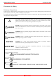
M30880T-EPB User’s Manual Precautions for Safety Precautions for Safety Definitions of Signal Words In both the user’s manual and on the product itself, several icons are used to insure proper handling of this product and also to prevent injuries to you or other persons, or damage to your properties. This chapter describes the precautions which should be taken in order to use this product safely and properly. Be sure to read this chapter before using this product.
M30880T-EPB User’s Manual Precautions for Safety WARNING Warnings for AC Power Supply: If the attached AC power cable does not fit the receptacle, do not alter the AC power cable and do not plug it forcibly. Failure to comply may cause electric shock and/or fire. Use an AC power cable which complies with the safety standard of the country. Do not touch the plug of the AC power cable when your hands are wet. This may cause electric shock. This product is connected signal ground with frame ground.
M30880T-EPB User’s Manual Precautions for Safety CAUTION Cautions to Be Taken for Turning On the Power: Turn ON the power of the emulator and user system as simultaneously as possible. Turn OFF the power of the emulator and user system as simultaneously as possible. Do not leave either the emulator or user system powered on, because of leakage current the internal circuits may be damaged. When turning ON the power again after shutting OFF the power, wait about 10 seconds.
M30880T-EPB User’s Manual Contents Contents Preface..........................................................................................................................................................................3 Important.......................................................................................................................................................................4 Precautions for Safety ......................................................................................
M30880T-EPB User’s Manual Contents 4. Hardware Specifications........................................................................................................................................77 4.1 Target MCU Specifications ..........................................................................................................................77 4.2 Differences between the Actual MCU and Emulator ...................................................................................
M30880T-EPB User’s Manual User Registration User Registration When you have purchased the emulator presented in this user's manual, please be sure to register it. As the hardware tool user registration FAX sheet is included with this manual, fill it in and FAX it to your local distributor or email the same contents to the following address. Your registered information is used for only after-sale services, and not for any other purposes.
M30880T-EPB User’s Manual Terminology Terminology Some specific words used in this user's manual are defined as follows: Emulator system This means an emulator system built around the PC7501 emulator. The PC7501 emulator system is configured with an emulator main unit, emulation probe, host machine and emulator debugger. Emulator main unit (Hereafter PC7501) This means an emulator main unit for M16C Family MCUs. Emulation probe This means the emulation probe (this product) for the M32C/88 Group MCUs.
M30880T-EPB User’s Manual 1. Outline 1. Outline This chapter describes the package components, the system configuration and the preparation for using this product for the first time. 1.1 Package Components The M30880T-EPB package consists of the following items. When unpacking it, check to see if your M30880T-EPB contains all of these items. Table 1.
M30880T-EPB User’s Manual 1. Outline 1.3 System Configuration 1.3.1 System Configuration Figure 1.1 shows a configuration of the M30880T-EPB system. Figure 1.1 System configuration (1) Emulation probe M30880T-EPB (this product) This emulation probe contains an evaluation MCU. (2) Converter board M30800T-PTC (included) This is a converter board for connecting to the user system (for 100-pin 0.65-mm-pitch LCC socket). For details, refer to "2.9 Connecting the User System" (page 29) REJ10J0497-0100Z Rev.
M30880T-EPB User’s Manual 1. Outline 1.3.2 Names and Functions of the PC7501 Upper Panel LEDs Figure 1.2 shows the names of the LEDs on the upper panel of the emulator. Figure 1.2 Names of the LEDs on the upper panel of the PC7501 (1) System Status LEDs The system status LEDs indicate the emulator PC7501's power supply, firmware operating status, etc. Table 1.3 lists the definition of each system status LED. Table 1.
M30880T-EPB User’s Manual 1. Outline (2) Target Status LEDs The target status LEDs indicate the target MCU's operating status and target board's power supply. Table 1.4 lists the definition of each target status LED. Table 1.4 Definitions of the target status LEDs Name POWER CLOCK RESET RUN WARNING Status ON OFF ON OFF ON OFF ON OFF ON OFF Meaning Power is supplied to the target MCU. Power is not supplied to the target MCU. Target MCU internal clock is oscillating.
M30880T-EPB User’s Manual 1. Outline 1.4 Specifications Tables 1.5 and 1.6 list the specifications of the M30880T-EPB. Table 1.
M30880T-EPB User’s Manual 1. Outline Table 1.6 M30880T-EPB specifications (2/2) Host machine interface Power supply to emulator Connection to user system (see "2.9 Connecting the User System" on page 29) - LPT parallel (ECP, EPP, Byte/compatibility and Nibble/compatibility modes) - USB (USB 1.1, full-speed) - LAN (10BASE-T) Supplied from included AC adapter (power supply voltage: 100--240 V, 50/60 Hz) For 144-pin 0.5-mm-pitch LQFP (144P6Q-A): M3T-FLX-144NSD (not included) For 100-pin 0.
M30880T-EPB User’s Manual 2. Setup 2. Setup This chapter describes the preparation for using this product, the procedure for starting up the emulator and how to change settings. 2.1 Flowchart of Starting Up the Emulator The procedure for starting up the emulator is shown in Figure 2.1. For details, refer to each section hereafter. And, when the emulator does not start up normally, refer to “5. Troubleshooting” (page 92). Check the package components. Refer to “1.1 Package Components (page 13).
M30880T-EPB User’s Manual 2. Setup 2.2 Installing the Emulator Debugger If the OS used in your host machine is Windows XP or 2000, this installation must be executed by a user with administrator rights. Be aware that users without administrator rights cannot complete the installation. Install the emulator debugger M3T-PD308F following the procedure described below. (1) Downloading the M3T-PD308F V.3.20 Release 1 Download the M3T-PD308F V.3.20 Release 1 from the URL below. http://www renesas.
M30880T-EPB User’s Manual 2. Setup 2.3 Connecting the Host Machine When connecting the emulator PC7501 to a host machine, you can choose your desired interface from LPT parallel interface, USB interface and LAN interface. Use the interface selection switch on the emulator PC7501's rear panel to specify your desired interface. Figure 2.2 shows the outline to connect each interface cable. Figure 2.2 Outline for interface cable connections REJ10J0497-0100Z Rev.1.
M30880T-EPB User’s Manual 2. Setup 2.4 Connecting the PC7501 Figure 2.3 shows how to connect the PC7501 and the emulation probe. M3T-FLX160-EPB M30880T-EPB Note: Connect the PCA7501EPBA board side to the M3T-FLX160-EPB. Figure 2.3 Connecting the PC7501 and emulation probe CAUTION Cautions for Connecting the PC7501: When connecting the emulation probe, be sure to hold the both sides of the emulation probe horizontally and insert it directly. Connect the PCA7501EPBA board to the M3T-FLX160-EPB.
M30880T-EPB User’s Manual 2. Setup 2.5 Connecting the Power Supply for the Emulator The power is supplied from AC adapter to the emulator PC7501. Here following explains how to connect the AC adapter. (1) (2) (3) (4) Turn OFF the power to the PC7501. Connect the DC cable of AC adapter to the PC7501. Connect the AC power cable to the AC adapter. Connect the AC power cable to the receptacle. CAUTION Cautions for AC Adapter: Use only the AC adapter included in PC7501 package.
M30880T-EPB User’s Manual 2. Setup 2.6 Turning ON the Power 2.6.1 Checking the Connections of the Emulator System Before turning the power ON, check the connection of the interface cable with host machine, PC7501, emulation probe, and user system. 2.6.2 Turning ON/OFF the Power Turn ON the power of the emulator and user system as simultaneously as possible. Turn OFF the power of the emulator and user system as simultaneously as possible.
M30880T-EPB User’s Manual 2. Setup 2.6.4 LED Display When the Emulator Starts Up Normally Figure 2.4 shows upper panel LED lighting status when the emulator started up properly. Check it when starting up the emulator system. - If this LED does not light, check the voltage of the user system. - Check power is supplied to all the power terminals. - When the user system is not connected, this LED does not light.
M30880T-EPB User’s Manual 2. Setup 2.7 Downloading Firmware 2.7.1 When It is Necessary to Download Firmware It is necessary to download the firmware in the cases listed below. Normally, the following are automatically detected when the emulator debugger is started up, and the firmware is downloaded.
M30880T-EPB User’s Manual 2. Setup 2.8 Self-check 2.8.1 Self-check Procedure To run the emulator self-check, do so as explained here below. While the self-check is in progress, LEDs will change as shown in Figure 2.6. (1) If the user system is connected, disconnect it. (2) Set the switches as the factory-settings to execute the self-check (see Table 2.1).
M30880T-EPB User’s Manual 2. Setup 2.8.2 If an Error is Detected in the Self-check If the self-check does not result normally (ERROR 1 to ERROR 4 in Figure 2.6), check the following. (1) Recheck the connection of the emulation probe and PC7501. (2) Redownload the proper firmware. IMPORTANT Note on the Self-check: If the self-check does not result normally (excluding user system errors), the emulation probe may be damaged. Then contact your local distributor. REJ10J0497-0100Z Rev.1.
M30880T-EPB User’s Manual 2. Setup 2.9 Connecting the User System There are eight ways available to connect the emulation probe to user systems as shown in Figure 2.7. Emulation probe 100-pin 144-pin 0.5-mm-pitch 0.65-mm-pitch 0.
M30880T-EPB User’s Manual 2. Setup 2.9.1 Connecting to a 100-pin LCC Socket When connecting the emulation probe to a 100-pin LCC socket (Yamaichi Electronics Co., Ltd.: IC61-1004-051 etc.) on the user system, following the procedure below. (1) Attach the CN2 side of the M30880T-EPB to the CN2 side of the M30800T-PTC. (2) Attach the M30800T-PTC to the 100-pin LCC socket. M3T-FLX160-EPB M30880T-EPB (1) (2) CN2 side M30800T-PTC 100-pin LCC socket No. 1 pin User system Figure 2.
M30880T-EPB User’s Manual 2. Setup 2.9.2 Connecting to a 100-pin 0.65-mm-pitch Foot Pattern (Part 1) Figure 2.9 shows how to connect the emulation probe to a 100-pin 0.65-mm-pitch foot pattern on the user system with the M3T-DUMMY100S (not included), and here following is its procedure. For details on the M3T-100LCC-DMS and M3T-DUMMY100S, refer to each user's manual. (1) (2) (3) (4) Attach the M3T-DUMMY100S to the user system. Attach the M3T-100LCC-DMS to the M3T-DUMMY100S.
M30880T-EPB User’s Manual 2. Setup 2.9.3 Connecting to a 100-pin 0.65-mm-pitch Foot Pattern (Part 2) Figure 2.10 shows how to connect the emulation probe to a 100-pin 0.65-mm-pitch foot pattern on the user system with the M3T-DIRECT100S (not included), and here following is its procedure. For details on the M3T-100LCC-DMS and M3TDIRECT100S, refer to each user's manual. (1) (2) (3) (4) Attach the M3T-DIRECT100S to the user system. Attach the M3T-100LCC-DMS to the M3T-DIRECT100S.
M30880T-EPB User’s Manual 2. Setup 2.9.4 Connecting to a 100-pin 0.65-mm-pitch Foot Pattern (Part 3) Figure 2.11 shows how to connect the emulation probe to a 100-pin 0.65-mm-pitch foot pattern on the user system with the M3T-FLX-100NRB (not included), and here following is its procedure. For details on the M3T-100LCC-DMS and M3T-FLX100NRB, refer to each user's manual. (1) (2) (3) (4) Attach the M3T-FLX-100NRB to the user system. Attach the M3T-100LCC-DMS to the M3T-FLX-100NRB.
M30880T-EPB User’s Manual 2. Setup 2.9.5 Connecting to a 100-pin 0.5-mm-pitch Foot Pattern (Part 1) Figure 2.12 shows how to connect the emulation probe to a 100-pin 0.5-mm-pitch foot pattern on the user system with the M3T-100LCC-QSD (not included), and here following is its procedure. For details on the M3T-100LCC-QSD, refer to its user's manual. (1) Attach the M3T-100LCC-QSD to the user system. (2) Attach the M30800T-PTC to the M30880T-EPB. (3) Attach the M30800T-PTC to the M3T-100LCC-QSD.
M30880T-EPB User’s Manual 2. Setup 2.9.6 Connecting to a 100-pin 0.5-mm-pitch Foot Pattern (Part 2) Figure 2.13 shows how to connect the emulation probe to a 100-pin 0.5-mm-pitch foot pattern on the user system with the M3T-FLX-100NSD (not included), and here following is its procedure. For details on the M3T-100LCC-DMS and M3T-FLX100NSD, refer to each user's manual. (1) (2) (3) (4) Attach the M3T-FLX-100NSD to the user system. Attach the M3T-100LCC-DMS to the M3T-FLX-100NSD.
M30880T-EPB User’s Manual 2. Setup 2.9.7 Connecting to a 100-pin 0.5-mm-pitch Foot Pattern (Part 3) Figure 2.14 shows how to connect the emulation probe to a 100-pin 0.5-mm-pitch foot pattern on the user system with the M3T-F160-100NSD (not included), and here following is its procedure. For details on the M3T-F160-100NSD, refer to its user's manual. (1) (2) (3) (4) (5) Mount the NQPACK100SD included with the M3T-F160-100NSD to the user system.
M30880T-EPB User’s Manual 2. Setup 2.9.8 Connecting to a 144-pin 0.5-mm-pitch Foot Pattern Figure 2.15 shows how to connect the emulation probe to a 144-pin 0.5-mm-pitch foot pattern on the user system with the M3T-FLX-144NSD (not included), and here following is its procedure. For details on the M3T-FLX-144NSD, refer to its user's manual. (1) (2) (3) (4) (5) Attach the NQPACK144SD included with the M3T-FLX-144NSD to the user system.
M30880T-EPB User’s Manual 2. Setup 2.10 Setting Switches 2.10.1 Setting Switches of Emulation Probe O N Set the switches of the emulation probe according to the condition. Figure 2.16 shows the positions of the switches of the M30880T-EPBM. M30880T-EPBM REV.B 8 7 6 5 4 3 2 C4 C3 C1 C2 RENESAS MADE IN JAPAN 1 SW5 JP1 INT P87 XCIN VCONT P86 NC VSS NC XOUT VCC1>2 AVCC AVSSEXT SW4 SW3 SW2 VCC1=2 SW1 Figure 2.16 Positions of the switches REJ10J0497-0100Z Rev.1.
M30880T-EPB User’s Manual 2. Setup (1) Setting SW1 to SW4 on the M30880T-EPBM Table 2.2 shows the settings of SW1 to SW4 on the M30880T-EPBM. Table 2.2 Switch settings of the M30880T-EPBM (SW1 to SW4) Switch SW1 Switch name AVCC AVSS Setting AVCC AVSS EXT Description INT Connects pins AVCC and AVSS of the MCU to the user system.
M30880T-EPB User’s Manual 2. Setup (2) Setting SW5 on the M30880T-EPBM Table 2.3 lists the examples of setting the switch SW5. It is necessary to change the setting if using the analog input port selection function of the A/D converter. Setting the SW5 enables to set each analog input pin for selecting an analog input port. When selecting AN00 to AN07 or AN20 to AN27 for the analog input port select bits (bit 2 and bit 1 of 0394h), set the pins used for A/D conversion to ON, the pins not used to OFF.
M30880T-EPB User’s Manual 2. Setup IMPORTANT Notes on Switch SW5: When setting the register below to use the analog input port selection function, you need to set the direction register of port P15 for a pin that performs A/D conversion to "input". And you need to set the function selection register of port P15 for a pin that performs A/D conversion to "I/O port".
M30880T-EPB User’s Manual 2. Setup 2.10.2 Selecting Clock Supply With this product, a clock supply can be set in Init dialog box of Emulator tab of the emulator debugger. Table 2.4 lists the factory-settings of each clock supply. Table 2.
M30880T-EPB User’s Manual 2. Setup 2) Replacing an Oscillator Circuit Board Remove the four screws of both sides of this product and lift off the upper cover (see Figure 2.17). Figure 2.17 Removing the upper cover REJ10J0497-0100Z Rev.1.
M30880T-EPB User’s Manual 2. Setup Unscrew the screw of the oscillator circuit board of the PC7501 and replace it (see Figure 2.18). The oscillator circuit board of the PC7501 is in the lower right corner of the board. Unscrew the screw securing the oscillator circuit board. Lift off the oscillator circuit board. Attach another oscillator circuit board to the connector. Secure the new oscillator circuit board with the screw. Figure 2.
M30880T-EPB User’s Manual 2. Setup 3) Using the Oscillator Circuit Bare Board To use this product at a frequency you like, build a desired oscillator circuit on the included OSC-2 oscillator circuit bare board. Figure 2.19 shows an external view of the OSC-2 oscillator circuit bare board and the connector pin locations. Figure 2.20 shows the circuitry of the oscillator circuit bare board OSC-2. Use the number of oscillator circuits recommended by the oscillator manufacturer.
M30880T-EPB User’s Manual 2. Setup (2) Using the Oscillator Circuit on the User System To operate this product with an oscillator circuit of the user system, input the oscillator output at 50% duty (within the operating range of the evaluation MCU) into pin XIN as shown in Figure 2.21. Pin XOUT should be open. Choose "External" in the emulator debugger to use this clock. Figure 2.21 External oscillator circuit In the oscillator circuit shown in Figure 2.
M30880T-EPB User’s Manual 2. Setup 2.10.3 A/D Conversion Bypass Capacitors O N There is a foot pattern on the M30880T-EPBM board for mounting bypass capacitors for the A/D conversion circuit. Mount applicable bypass capacitors as occasion demands. Figure 2.23 shows where they are installed. M30880T-EPBM REV.
M30880T-EPB User’s Manual 3. Usage (How to Use the Emulator Debugger) 3. Usage (Emulator Debugger) This chapter describes how to start up the emulator debugger and how to use the major windows. 3.1 Starting Up the Emulator Debugger (Init Dialog Box) To launch the emulator debugger, click the Start menu of Windows and then select Program (P) >> [RENESAS-TOOLS] >> [PD308F V.xx.xx Release x] >> [PD308F]. When the emulator debugger started up, the Init dialog box appears. (1) MCU tab 1.
M30880T-EPB User’s Manual 3. Usage (How to Use the Emulator Debugger) 3. Specifying the communication interface (LAN communication) Specifying the communication interface (LAN communication) For selecting the LAN communication, click the radio button “LAN” of the MCU tab. Specify the IP address of the emulator at the IP address area. Specify the IP address by one byte of decimal number separating each four bytes with a period. Specify the port number at the Port area. 4.
M30880T-EPB User’s Manual 3. Usage (How to Use the Emulator Debugger) 5. Using or not using the address match break function Using or not using the address match break function Specify whether or not to use the address match break function. - To use the address match break function (default), select the check box (marked by a check mark when selected). In this case, the address match interrupt is used by the emulator, and cannot be used in the user program.
M30880T-EPB User’s Manual 3. Usage (How to Use the Emulator Debugger) 7. Using or not using the CPU rewrite mode Using or not using CPU rewrite mode Specify whether or not to debug in CPU rewrite mode. To debug the user system that uses CPU rewrite mode, select the check box. This option can be selected or deselected only when you are starting up the emulator debugger.
M30880T-EPB User’s Manual 3. Usage (How to Use the Emulator Debugger) (2) Debugging Information tab 1. Specifying the compiler used and the object format Specifying the compiler used and the object format Specify the compiler you are using and the format of the object file output by the compiler. - Compiler Select the compiler you are using. (By default, the C compiler from Renesas is selected.) - Object Format Select the format of the object file that is output by the compiler you are using.
M30880T-EPB User’s Manual 3. Usage (How to Use the Emulator Debugger) (4) Emulator tab 1. Specifying the target clock Specifying the target clock Specify the clock sources supplied to the MCU (main clock and sub clock). Select the appropriate clock sources according to the clock used by your target MCU. - Internal (default) Emulator PC7501’s internal clock - External User system clock - Generated Clock created in PC7501 The option you have specified here remains effective the next time you start up.
M30880T-EPB User’s Manual 3. Usage (How to Use the Emulator Debugger) (5) Resume tab 1. Automatically executing a script command Automatically executing a script command To automatically execute a script command when starting up the debugger, click the “Refer...” button and specify the script file to be executed. Clicking the “Refer...” button brings up a file selection dialog box. The script file you have selected is displayed in the Init File: section of the dialog box shown here.
M30880T-EPB User’s Manual 3. Usage (How to Use the Emulator Debugger) 3.2 Starting Up the Emulator Debugger (EMEM Dialog Box) (1) Status tab 1. Specifying the processor mode Specifying the processor mode Select the Single-chip Mode. IMPORTANT Notes on Selecting a Processor Mode: An available processor mode is single-chip mode only. Therefore, do not select any other processor mode. When setting single-chip mode, the level of pin CNVSS of the MCU status should be "L".
M30880T-EPB User’s Manual 3. Usage (How to Use the Emulator Debugger) 2. Referring to the MCU Status Referring to the MCU Status It shows the status of each MCU pin. Check it to see if the MCU status matches the selected processor mode. If a slider of any pin is at the center, it means that the pin status is indeterminate. IMPORTANT Notes on Selecting a Processor Mode: The MCU status is shown in “MCU Status” of the EMEM dialog box. Check that the level of pin CNVSS of the MCU status is “L”.
M30880T-EPB User’s Manual 3. Usage (How to Use the Emulator Debugger) (2) Emulation Memory tab 1. Setting the Bank Address of the Debug Monitor Setting the Bank Address of the Debug Monitor The debug monitor uses contiguous 64 KB as a work area of the emulator. Specify the bank address of the debug monitor. (e.g.
M30880T-EPB User’s Manual 3. Usage (How to Use the Emulator Debugger) 2. Emulation Memory Allocation as Expansion Area Emulation Memory Allocation as Expansion Area Because the available processor mode is the single-chip mode only, select “No Use” in “Map”. REJ10J0497-0100Z Rev.1.
M30880T-EPB User’s Manual 3. Usage (How to Use the Emulator Debugger) (3) Flash Clear tab 1. Setting to clear the MCU’s internal flash ROM Setting to clear the MCU’s internal flash ROM Specify whether or not you want the MCU’s internal flash ROM to be cleared when downloading the user program or data. (When cleared, the content of the flash ROM is initialized to 0xFF.) The MCU’s internal flash ROM is listed in block units. - Any block which has had its check box selected is not cleared when downloading.
M30880T-EPB User’s Manual 3. Usage (How to Use the Emulator Debugger) 3.3 Program Window (1) Downloading the program 1. Initial screen of the program window Initial screen of the program window The program window is a window that always shows the content of the source file corresponding to the current position of the program counter. It automatically opens when the emulator starts up. The program counter position is identified by the yellow background color.
M30880T-EPB User’s Manual 3. Usage (How to Use the Emulator Debugger) (2) Program execution 1. Resetting the user program RESET Resets the program. 2. Executing the user program GO Executes the program from the current PC position. STEP Single-steps the program, stepping subroutines. OVER Single-steps the program, skipping over subroutines. RETURN Executes the program up to the high-order subroutine. 3. Stopping the user program STOP Stops the program. 4.
M30880T-EPB User’s Manual 3. Usage (How to Use the Emulator Debugger) (3) Setting breakpoints 1. Screen after breakpoint setup Breakpoint setup screen There are three types of breakpoints as described below. - Address match breakpoint (A) This breakpoint can be set only when you chose to use the address match break function on the MCU tab of the Init dialog box. A breakpoint can be set or cleared by double-clicking in the breakpoint display area. Up to eight breakpoints can be set.
M30880T-EPB User’s Manual 3. Usage (How to Use the Emulator Debugger) (4) Executing up to the cursor position (Come command) 1. Specifying the Come command Setup procedure for executing COME command (1) Click the line in the program display area at which you want the program to execute. (2) Click the Come button. 2. After the Come command has finished REJ10J0497-0100Z Rev.1.
M30880T-EPB User’s Manual 3. Usage (How to Use the Emulator Debugger) 3.4 Hardware Breakpoint Setting Window (1) Breakpoint setup dialog box 1. Opening the hardware breakpoint setup dialog box Hardware Break Point Clicking this button opens the hardware breakpoint setup dialog box. 2. Hardware Break Point Setting Window in initial state H/W breakpoint Setting Window in initial state Select the “Enable H/W Break” check box, and this break function will be enabled, allowing you to set hardware breakpoints.
M30880T-EPB User’s Manual 3. Usage (How to Use the Emulator Debugger) 4. Opening the break event setting dialog box Specifying the event type Click to select the event type you want to set. - FETCH Detects an instruction prefetch. - DATA ACCESS Detects a memory access. - BIT SYMBOL Detects a bit access. - INTERRUPT Detects an interrupt occurrence or interrupt termination. - TRIGGER Detects a signal from the external trace signal input cable. (2) When FETCH is selected 1.
M30880T-EPB User’s Manual 3. Usage (How to Use the Emulator Debugger) (3) When DATA ACCESS is selected 1. Window for setting the address Setting the address You can set eight conditions, e.g., a specified address, a specified address range, etc. 2. Window for setting data Setting data You can set eight conditions, e.g., a specified data, a specified data range, etc. Setting the access condition You can set three conditions, e.g., read, write, and read/write.
M30880T-EPB User’s Manual 3. Usage (How to Use the Emulator Debugger) 3. Example Data Settings Event setting for even-address word access Setting a break event MOV.W R0,512h(R0=0203h) A1 High-order and low-order data effective Event setting for odd-address word access MOV.
M30880T-EPB User’s Manual 3. Usage (How to Use the Emulator Debugger) (4) Setting the combinatorial event condition 1. Window for setting the combinatorial event condition Setting the combinatorial event condition There are following four conditions that you can choose for the combinatorial events. - AND The program breaks when all of the specified events occur. - AND (Same Time) The program breaks when the specified events occur at the same time.
M30880T-EPB User’s Manual 3. Usage (How to Use the Emulator Debugger) 3.5 Trace Window (1) Trace window 1. Trace window Menu OptionalWindows Menu item Trace Window Function Opens the trace window. Trace window The trace window is used to show the results of real-time trace measurements. It has the following four display modes: - Bus mode Bus information per cycle can be inspected. The contents are displayed in order of execution paths.
M30880T-EPB User’s Manual 2. Trace window (bus display) Bus display 3. Usage (How to Use the Emulator Debugger) Explanation of the trace window (bus display) The following explains the displayed contents, from left to right. - Address Shows the status of the address bus. - Data Shows the status of the data bus. - BUS Shows the width of the external data bus. In the present emulator, only “16b” for 16 bits wide bus is displayed. - BHE* Shows the status (0 or 1) of the BHE (Byte High Enable) signal.
M30880T-EPB User’s Manual 3. Usage (How to Use the Emulator Debugger) (2) Suspending and resuming trace measurement 1. Suspending trace measurement Stop Click this toolbar button to suspend the trace measurement in progress. 2. Resuming trace measurement Re-Start Click this toolbar button to resume the trace measurement in progress. REJ10J0497-0100Z Rev.1.
M30880T-EPB User’s Manual 3. Usage (How to Use the Emulator Debugger) (3) Trace point setup dialog box 1. Opening the trace point setup dialog box Trace Point Clicking this toolbar button opens the trace point setting window. 2. Trace Point Setting Window in initial state Trace Point Setting Window in initial state Be sure to enable the trace point function in the Init dialog box before you set up in this window. Here, you can set events in the same way as for the hardware breakpoints.
M30880T-EPB User’s Manual 3. Usage (How to Use the Emulator Debugger) 3. Specifying a trace range Specifying a trace range You can specify a trace range for the trace event. - Break 256K cycles of instruction execution before the user program stopped is recorded. - Before 256K cycles of instruction execution before a trace point condition was met is recorded. - About 128K cycles of instruction execution before and after a trace point condition was met is recorded.
M30880T-EPB User’s Manual 3. Usage (How to Use the Emulator Debugger) 3.6 RAM Monitor Window (1) RAM monitor window 1. RAM monitor window Menu Menu item BasicWindows RAM Monitor Window Function Opening the RAM monitor window RAM monitor window This window shows changes of memory contents while the user program is executed. This is accomplished by using the real-time RAM monitor function, and the memory contents corresponding to the RAM monitor area are displayed in dump form.
M30880T-EPB User’s Manual 3. Usage (How to Use the Emulator Debugger) (2) RAM monitor area setting window 1. Opening RAM monitor area setting window Base Clicking this toolbar button opens the RAM monitor area setting window. 2. RAM monitor area setting window in initial state RAM Monitor Area Setting Window in initial state By default, the monitor area is set to 000400h through 0007FFh. To change it, click the line you want to set. REJ10J0497-0100Z Rev.1.
M30880T-EPB User’s Manual 3. Usage (How to Use the Emulator Debugger) 3. RAM monitor area setting dialog box Specifying the start address You can set the start address of the RAM area to be monitored. Specifying the size You can set the size to be monitored by specifying the number of blocks from the start address. One block is 256 bytes in size. 4.
M30880T-EPB User’s Manual 4. Hardware Specifications 4. Hardware Specifications This chapter describes specifications of this product. 4.1 Target MCU Specifications Table 4.1 lists the specifications of target MCUs which can be debugged with this product. Table 4.1 Specifications of target MCUs for the M30880T-EPB Item Applicable MCU Applicable MCU mode Maxi. ROM/RAM capacity Operating voltage/frequency Description M32C/88 Group Single-chip mode 1.
M30880T-EPB User’s Manual 4. Hardware Specifications 4.2 Differences between the Actual MCU and Emulator Differences between the actual MCU and emulator are shown below. When debugging the MCU using this product, be careful about the following precautions. IMPORTANT Note on Differences between the Actual MCU and Emulator: Operations of the emulator system differ from those of actual MCUs as listed below.
M30880T-EPB User’s Manual 4. Hardware Specifications IMPORTANT Notes on Reset Vector Area: For a reset vector area, memory of the emulator is always selected regardless of the setting of the EMEM dialog box. A reset vector area can be changed only when a program is stopped. Notes on Stack Area: With this product, a maximum 20 bytes of the user stack is consumed as a work area. Therefore, ensure the +20 byte maximum capacity used by the user program as the user stack area.
M30880T-EPB User’s Manual 4. Hardware Specifications IMPORTANT Note on DMAC II Transfer Completion Interrupts: You can use DMAC II transfer completion interrupts during program execution only. Do not generate DMAC II transfer completion interrupts when you use any function but program execution. Note on Final Evaluation: Be sure to evaluate your system with an evaluation MCU. Before starting mask production, evaluate your system and make final confirmation with a CS (Commercial Sample) version MCU.
M30880T-EPB User’s Manual 4. Hardware Specifications 4.3 Connection Diagrams Figures 4.1 and 4.2 show the connection diagrams of the M30880T-EPB. These connection diagrams mainly show the interface section. The signals not shown in Figures 4.1 and 4.2 connect the evaluation MCU and the user system directly. The circuits not connected to the user system such as the emulator's control system are omitted. Table 4.2 shows IC electric characteristics of this product for reference purposes.
M30880T-EPB User’s Manual AP150 * AP151 * AP152 * AP153 * 4.
M30880T-EPB User’s Manual 4. Hardware Specifications 4.4 External Dimensions 4.4.1 External Dimensions of the Emulation Probe Figure 4.3 shows external dimensions of the M30880T-EPB connected with the M30800T-PTC and LCC socket. 85.0 10.0 9.0 60.0 21.0 9.0 PCA7501EPBA REV.A 10.0 MADE IN JAPAN 30.0 5.5 10.8 15.0 55.0 16.3 15.0 Unit : mm Figure 4.3 External dimensions of the emulation probe REJ10J0497-0100Z Rev.1.
M30880T-EPB User’s Manual 4. Hardware Specifications 4.4.2 External Dimensions of the M30800T-PTC Figure 4.4 shows external dimensions of the converter board M30800T-PTC for a 100-pin QFP (100P6S). Unit : mm Figure 4.4 External dimensions of the M30800T-PTC REJ10J0497-0100Z Rev.1.
M30880T-EPB User’s Manual 4. Hardware Specifications 4.4.3 External Dimensions of the M3T-F160-100NSD Figure 4.5 shows external dimensions of the converter board M3T-F160-100NSD for a 100-pin LQFP (100P6Q). Unit : mm Figure 4.5 External dimensions of the M3T-F160-100NSD 4.4.4 External Dimensions of the M3T-FLX-144NSD Figure 4.6 shows external dimensions of the converter board M3T-FLX-144NSD for a 144-pin LQFP (144P6Q). Unit : mm Figure 4.
M30880T-EPB User’s Manual 4. Hardware Specifications 4.5 Notes on Using This Product Notes on using this product are listed below. Be sure to read these notes before using this product. IMPORTANT Notes on Downloading Firmware: Before using this product for the first time, it is necessary to download the dedicated firmware (control software built into the PC7501). Please note that, to do this, it is necessary to start up the PC7501 in maintenance mode. For firmware download procedures, see "2.
M30880T-EPB User’s Manual 4. Hardware Specifications IMPORTANT Notes on Clock Supply to an MCU: Clock can be supplied to the evaluation MCU in one of the following three ways. This is determined by emulator debugger clock selection. (1) When Internal is selected: The clock generated by the oscillation circuit in the PC7501 is supplied to the evaluation MCU. The clock is continually supplied to the evaluation MCU regardless of "user system clock status" and "user program execution status".
M30880T-EPB User’s Manual 4. Hardware Specifications IMPORTANT Notes on EMEM Dialog Box: Observe the following when setting up EMEM dialog box of the emulator debugger. (1) Debug Monitor Bank Address The default value of Debug Monitor Bank Address is "F0". To set single-chip mode, internal flash memory is automatically allocated in F000h--FFFFh and F80000h--FFFFFFh. The specified value becomes effective after restarting the system.
M30880T-EPB User’s Manual 4. Hardware Specifications IMPORTANT Notes on Debugging in CPU Rewrite Mode: To debug a program in CPU rewrite mode, select the check box "Debug the program using the CPU Rewrite Mode" in the MCU tab of the Init dialog box. When you do not debug a program in CPU rewrite mode, clear the check box. When you debug a program in CPU rewrite mode, the block 0 area (FFF000h--FFFFFFh) must not be rewritten. Otherwise, the emulator will be out of control.
M30880T-EPB User’s Manual 4. Hardware Specifications IMPORTANT Note on Protect Resistor: A protect is not canceled when protect register bit 2 (PRC2), which enables writing in the port P9 direction register and the function select register A3, is changed with the below procedure.
M30880T-EPB User’s Manual 4. Hardware Specifications IMPORTANT Notes on A/D Conversion: When setting the register below to use the analog input port selection function, you need to set the direction register of port P15 for a pin that performs A/D conversion to "input". And you need to set the function selection register of port P15 for a pin that performs A/D conversion to "I/O port".
M30880T-EPB User’s Manual 5. Troubleshooting 5. Troubleshooting This chapter describes how to troubleshoot when this product does not work properly. 5.1 Flowchart to Remedy the Troubles Figure 5.1 shows the flowchart to remedy the troubles from when power to the emulator is activated until the emulator debugger starts up. Check this while the user system is disconnected. For the latest FAQs visit the Renesas Tools Homepage. http://www.renesas.
M30880T-EPB User’s Manual 5. Troubleshooting 5.2 When the Emulator Debugger Does Not Start Up Properly (1) When the LEDs of the PC7501 Do Not Display Normally Table 5.1 Errors LEDs show and their checkpoints LEDs do not light up. Connection to the user system - All LEDs remain lit. - Error Checkpoint Check that the power cable is connected. See "2.5 Connecting the Power Supply for the Emulator" (page 23) and the user's manual of the PC7501. Recheck the connection between the PC7501 and this product.
M30880T-EPB User’s Manual 5. Troubleshooting (2) EMEM Dialog Box Does Not Appear at Debugger Startup Table 5.2 Checkpoints of errors at debugger startup Error Communication error occurred. Data was not sent to the target. Checkpoint Check all emulator debugger settings, interface cable settings and switches on the rear of the PC7501 match. See the user's manuals of PC7501 and emulator debugger. User system cannot be properly built. (1) Download the proper firmware. See "2.
M30880T-EPB User’s Manual 5. Troubleshooting (3) Errors Occur at Debugger Startup Table 5.3 Checkpoints of errors at debugger startup Error Target MCU is uncontrollable. Checkpoint (1) Check that the NQPACK etc. mounted on the user system is soldered properly. (2) Check that the connector is installed properly to the user system. (3) Check pin NMI* is held high. (4) The program may be uncontrollable in areas where memory is not allocated. REJ10J0497-0100Z Rev.1.
M30880T-EPB User’s Manual 5. Troubleshooting 5.3 How to Request for Support After checking the items in "5 Troubleshooting", fill in the text file the installer of the emulator debugger generates in the following directory and email to your local distributor. \SUPPORT\product-name\SUPPORT.
M30880T-EPB User’s Manual 6. Maintenance and Guarantee 6. Maintenance and Guarantee This chapter describes how to maintenance, repair provisions and how to request for repair. 6.1 User Registration When you purchase our product, be sure register as a user. For user registration, refer to “User registration” (page 11) of this user's manual. 6.2 Maintenance (1) If dust or dirt collects on any equipment of your emulation system, wipe it off with a dry soft cloth.
M30880T-EPB User’s Manual 6. Maintenance and Guarantee (3) Expiration of the repair period When a period of one year elapses after the model was dropped from production, repairing products of the model may become impossible. (4) Transportation fees at sending your product for repair Please send your product to us for repair at your expense. 6.5 How to Make Request for Repair If your product is found faulty, follow the procedure below to send your product for repair.
Emulation Probe for M32C/88 Group M30880T-EPB User's Manual Publication Date: Jan. 16, 2005 Rev.1.00 Published by: Sales Strategic Planning Div. Renesas Technology Corp. Edited by: Microcomputer Tool Development Department Renesas Solutions Corp. © 2005. Renesas Technology Corp. and Renesas Solutions Corp., All rights reserved. Printed in Japan.
M30880T-EPB User's Manual