
Datasheet


M32C/87 Group (M32C/87, M32C/87A, M32C/87B) 1. Overview
REJ03B0127-0151 Rev.1.51 Jul 31, 2008
Page 2 of 85
1.1.2 Specifications
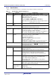
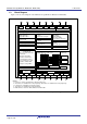
Tables 1.1 to 1.4 list the specifications of the M32C/87 Group (M32C/87, M32C/87A, M32C/87B).
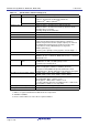
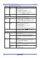
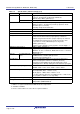
Table 1.1 Specifications (144-Pin Package) (1/2)
Item Function Specification
CPU Central processing
unit
M32C/80 core (multiplier: 16 bits × 16 bits → 32 bits
multiply-addition operation instructions: 16 × 16 + 48 → 48 bits)
• Basic instructions: 108
• Minimum instruction execution time:
31.3 ns (f(CPU) = 32 MHz, VCC1 = 4.2 to 5.5 V)
41.7 ns (f(CPU) = 24 MHz, VCC1 = 3.0 to 5.5 V)
• Operating modes: Single-chip mode, memory expansion mode,
and microprocessor mode
Memory ROM, RAM, data
flash
See Tables 1.5 to 1.7 Product List.
Power Supply Voltage Detection Vdet3 detection function, Vdet4 detection function,
cold start/warm start determination function
External Bus
Expansion
Bus/memory
expansion function
• Address space: 16 Mbytes
• External bus interface: 1 to 7 wait states can be inserted,
4 chip select outputs, 3 V and 5 V interfaces
• Bus format: Switchable between separate bus and multiplexed
bus formats, switchable data bus width (8-bit or 16-bit)
Clock Clock generation
circuits
• 4 circuits:
Main clock, sub clock, on-chip oscillator,
PLL frequency synthesizer
• Oscillation stop detection:
Main clock oscillation stop detection function
• Frequency divider circuit:
Dividing ratio selectable among 1, 2, 3, 4, 6, 8, 10, 12, 14, 16
• Low power consumption features: Wait mode, stop mode
Interrupts • Interrupt vectors: 70
• External interrupt inputs: 14 (NMI
, INT × 9, key input × 4)
• Interrupt priority levels: 7
Watchdog Timer 15-bit × 1 channel (with prescaler)
DMA DMAC • 4 channels, cycle steal method
• Trigger sources: 43
• Transfer modes: 2 (single transfer and repeat transfer)
DMACII • Can be activated by all peripheral function interrupt sources
• Transfer modes: 2 (single transfer and burst transfer)
• Immediate transfer, calculation transfer, and chain transfer
functions
Timer Timer A 16-bit timer × 5
Timer mode, event counter mode, one-shot timer mode,
pulse width modulation (PWM) mode,
Event counter 2-phase pulse signal processing (2-phase
encoder input) × 3
Timer B 16-bit timer × 6
Timer mode, event counter mode, pulse period measurement
mode, pulse width measurement mode
Timer function for
3-phase motor
control
3-phase inverter control × 1 (using timer A1, timer A2, timer A4,
and timer B2)
On-chip dead time timer