
User`s manual


( 38 / 74 )
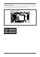
3.5.4 Connecting to a 100-pin 0.65-mm-pitch Foot Pattern (Part 3)
Here following is a procedure of connecting to a 100-pin 0.65-mm-pitch foot pattern on the user system using the
M3T-FLX-100NRB (not included). For details on the M3T-100LCC-DMS (not included) and M3T-FLX-100NRB,
refer to each user's manual.
(1) Attach the NQPACK100RB included with the M3T-FLX-100NRB to the user system.
(2) Attach the YQPACK100RB included with the M3T-FLX-100NRB to the NQPACK100RB and secure it with the
YQ-GUIDE's.
(3) Attach the M3T-FLX-100NRB to the YQPACK100RB.
(4) Attach the M3T-100LCC-DMS to the M3T-FLX-100NRB.
(5) Attach the CN2 side of the M30800T-PTC to the J4 side of the M306NKT-EPB.
(6) Attach the M30800T-PTC to the M3T-100LCC-DMS.
Figure 3.14 Connecting to a 100-pin 0.65-mm-pitch foot pattern (Part 3)
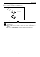
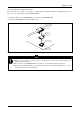
CAUTION
Notes on Connecting the User System:
z Take care not to attach a converter board in a wrong direction. It may cause a fatal damage to the
emulator and targets system.
z The connectors of the M30800T-PTC are guaranteed for only 50 insertion/removal iterations.
z The connectors of the M3T-100LCC-DMS and M3T-FLX-100NRB are guaranteed for only 20
insertion/removal iterations.
M3T-FLX160-EPB
M306NKT-EPB
M3T-100LCC-DMS
(not included)
CN2 side
(5)
M30800T-PTC
(1)
100-pin 0.65-mm-pitch
(100P6S-A) foot pattern
No. 1 pin
User target
M3T-FLX-100NRB
(not included)
FLASH MCU etc.
On-board evaluation
*: These four items are available in one package.
YQPACK100RB
NQPACK100RB
HQPACK100RB168
(not included)
These corners are not round.
(2)
(3)
(6)
(4)
YQ-GUIDE (x4)
*