M302N2T-PRB Pod Probe for M302N1 and M302N2 Group MCUs User's Manual Rev.1.
• TQPACK080SB, TQSOCKET080SBG, YQPACK056SB, NQPACK056SB and YQ-GUIDE are products of Tokyo Eletech Corporation. Keep safety first in your circuit designs! • Renesas Technology Corporation and Renesas Solutions Corporation put the maximum effort into making semiconductor products better and more reliable, but there is always the possibility that trouble may occur with them. Trouble with semiconductors may lead to personal injury, fire or property damage.
Preface The M302N2T-PRB is a pod probe for the M302N1 and M302N2 Group of Renesas 16-bit MCUs. The M302N2T-PRB is used by connecting to the PC4701 emulator main unit and the M30200T-RPD-E emulation pod main unit. This manual mainly explains specifications and how to set up the M302N2T-PRB. For detail information about the emulator main unit, emulation pod main unit, and emulator debugger, refer to each user's manual.
Contents Terminology ........................................................................................................................... 5 Chapter 1. Precautions for Safety ........................................................................................... 7 1.1 Safety Symbols and Meanings .............................................................................. 8 Chapter 2. Preparation .....................................................................................................
Terminology Some specific words used in this user's manual are defined as follows: Emulation pod main unit This means the emulation pod M30200T-RPD-E for the M16C/20 Series MCUs. Emulator debugger This means a software tool M3T-PD30 to control the emulator from the host machine through an interface. Emulator main unit (Hereafter PC4701) This means the generic name for emulators for 8 and 16-bit MCUs. For details on specific models of PC4701, visit Renesas Tools Homepage at http://www.renesas.
MEMO ( 6 / 38 )
Chapter 1. Precautions for Safety This chapter describes precautions for using this product safely and properly. For precautions for the emulator main unit, the emulation pod main unit and the emulator debugger, refer to each user's manual included with your product. 1.1 Safety Symbols and Meanings ..................................................................................................... 8 IMPORTANT Note on Final Evaluation ......................................................................
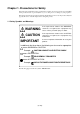
Chapter 1. Precautions for Safety In both the user's manual and on the product itself, several icons are used to insure proper handling of this product and also to prevent injuries to you or other persons, or damage to your properties. This chapter describes the precautions which should be taken in order to use this product safely and properly. Be sure to read this chapter before using this product. 1.
IMPORTANT Note on Final Evaluation: • Be sure to evaluate your system and make final confirmation with an CS (Commercial Sample) version MCU. Note on Differences from Actual MCUs: • Operations of the emulator system differ from those of mask MCUs as listed below. (1) Initial values of internal resource data at power-on (2) Internal memories (ROM and RAM) capacities, etc. With this emulator system, "INT" (emulation memory ON) is the default for mapping areas other than the SFR area (addresses 000h - 3FFh).
IMPORTANT Note on Clock Supply to the MCU: • Clock can be supplied to the evaluation MCU in one of the following two ways. This is determined by emulator debugger clock selection. (1) When Internal is selected: The clock generated by the oscillation circuit in the emulation pod is supplied to the evaluation MCU. The clock is continually supplied to the evaluation MCU regardless of "target system clock status" and "user program execution status".
IMPORTANT Note on the Work Area: • When using this product, set to "2C00h" as a start address of the work area at the time of starting up the emulator debugger (set by "F/W and Work Area" tab*1 of Init dialog). In this case, the emulator system uses the area below as a work area. 02C00h - 02C0Fh: Work area *1 Supported by M3T-PD30 Ver.4.00 or later Note on MAP References and Settings: • When starting up the M30200T-RPD-E, initial MAP settings are as follows. Use generally the M30200T-RPD-E in this setting.
MEMO ( 12 / 38 )
Chapter 2. Preparation This chapter describes the package components, the system configuration and the preparation for using this product for the first time. 2.1 Package Components.................................................................................................................. 14 2.2 Other Tool Products Required for Development........................................................................ 14 2.3 System Configuration ...............................................................
Chapter 2. Preparation 2.1 Package Components This product consists of the following items. When unpacking, check to see if your product package contains all of these items. Table 2.1 Package components Item Quantity M302N2T-PRB pod probe for M302N1 and M302N2 Group MCUs 1 Screws (screws for fixing pod probe: pre-installed to the pod probe) 2 FLX-80QSB converter board for 80-pin 0.
2.3 System Configuration Figure 2.1 System configuration Products (1) and (2) shown in Figure 2.1 are included with this product. Get (3) and (4) separately. (1) Pod probe (M302N2T-PRB) This pod probe is equipped with the evaluation MCU (M302NX-OTHERS). (2) FLX-80QSB (converter board for 80-pin 0.65-mm-pitch QFP) This is a pitch converter board (included) used for evaluating the M302N2 Group MCUs. (3) DIRECT80S (converter board for 80-pin 0.
MEMO ( 16 / 38 )
Chapter 3. Setting Up This chapter describes switch settings required for using this product and how to connect this product to the PC4701 and the target system. 3.1 Switch Settings ........................................................................................................................... 18 3.2 A-D Conversion Bypass Capacitor ............................................................................................ 19 3.3 Connecting the M30200T-RPD-E ....................................
Chapter 3. Setting Up With this product, it is necessary to set the following according to your target system. • Switching ports (P70 and P71) and sub-clock • Mounting the A-D conversion bypass capacitor 3.1 Switch Settings It is necessary to set the switches of the FLX64-PRB for debugging according to the target system. Figure 3.1 shows the positions of the switches of the FLX64-PRB, and Table 3.1 shows the switch settings. Figure 3.1 Positions of the switches and their factory-settings Table 3.
3.2 A-D Conversion Bypass Capacitor This product has foot patterns on the board for mounting a bypass capacitor for the A-D converter circuit. Mount a suitable bypass capacitor as occasion demands. Figure 3.2 shows the position of the bypass capacitor. Figure 3.
3.3 Connecting the M30200T-RPD-E The emulation pod for M302N1 and M302N2 Group MCUs consists of the two products, the M30200T-RPD-E emulation pod and the M302N2T-PRB pod probe. Figures 3.3 and 3.4 show how to connect the M30200T-PRB and how to remove it, respectively. (1) Connect the J1 and J2 connectors of the M302N2TPRB to the J3 and J4 connectors of the FLX64-PRB. (2) Fix the FLX64-PRB by the two screws. Figure 3.3 Connecting pod probe M302N2T-PRB (1) Unscrew the two screws of the M302N2T-PRB.
3.4 Connecting the Target System There are three ways available to connect this product to target systems as shown in Figure 3.5. Figure 3.5 Connecting the target system CAUTION Notes on Connecting the Target System: • Always shut OFF power before connecting the target system. • The small connectors of the M302N2T-PRB (J3 and J4) are guaranteed for only 20 insertion/removal iterations.
The emulation pod for M302N2 Group needs the pitch converter board FLX-80QSB or DIRECT80S and the emulation pod for M302N1 Group needs the pitch converter board M302N1T-56FPB. Figures 3.6 and 3.7 show how to connect the pitch converter board FLX-80QSB for 80-pin QFP and how to connect the pitch converter board M302N1T-56FPB for 56-pin QFP, respectively. (1) Mount the included TQPACK080SB to the target system. (2) Connect the included TQSOCKET080SBG to the TQPACK080SB.
Figure 3.7 shows how to connect the pitch converter board M302N1T-56FPB for 56-pin 0.65-mmpitch QFP. (1) Mount the NQPACK056SB to the target system. (2) Fix the YQPACK056SB to the NQPACK056SB using the included YQ-GUIDE's. (3) Connect the M302N1T-56FPB along the YQGUIDE's. (4) Connect the M302N2T-PRB. Figure 3.
3.5 Procedures for Making MCU File for M3T-PD30 It is necessary to change the contents of the MCU file according to the MCU to be developed. Make the MCU file M302N1.MCU for M302N1 Group and M302N2.MCU for M302N2 Group and store it in the following directory (the directory varies depending on the version of the M3T-PD30). • M3T-PD30 Ver.5.00 or later: Store the MCU file in the "Mcufiles" folder in the directory same as emulator debugger M3T-PD30 is stored. • M3T-PD30 Ver.4.
Chapter 4. Specifications This chapter describes specifications of this product. 4.1 Specifications ............................................................................................................................. 26 4.2 External Dimensions .................................................................................................................. 27 (1) External Dimensions of Pod Probe .......................................................................................
Chapter 4. Specifications 4.1 Specifications Table 4.1 lists the specifications of the M302N2T-PRB. Table 4.1 Specifications of M302N2T-PRB Emulator PC4701 Emulation pod main unit M30200T-RPD-E Applicable MCUs M302N1 and M302N2 Group MCUs Usable MCU mode Single-chip mode Emulation memory 1 MB Max. operating frequency XIN = 10.0 MHz (no-wait, 4.2 - 5.5 V) Operating power voltage 4.2 - 5.5 V Stack capacity for the emulator Max.
4.2 External Dimensions (1) External Dimensions of Pod Probe Figure 4.1 shows the external dimensions of the pod probe M302N2T-PRB. Unit: mm Figure 4.1 External dimensions of the pod probe M302N2T-PRB (2) External Dimensions of Converter Board (FLX-80QSB) Figure 4.2 shows the external dimensions and a sample foot pattern of the pitch converter board FLX80QSB for 80-pin 0.65-mm-pitch QFP. Unit: mm Figure 4.
(3) External Dimensions of Converter Board (M302N1T-56FPB) Figure 4.3 shows the external dimensions and a sample foot pattern of the pitch converter board M302N1T-56FPB for 56-pin 0.65-mm-pitch QFP. Unit: mm Figure 4.
Chapter 5. Troubleshooting This chapter describes how to troubleshoot when this product does not work properly. 5.1 When the Emulator Debugger Does Not Start Up Properly....................................................... 30 (1) When the LED Display of PC4701 is Abnormal .................................................................. 30 (2) Errors Occur When Starting Up the Emulator Debugger (When the target system is connected) ..................................................................
Chapter 5. Troubleshooting When this product does not work properly, check the following. 5.1 When the Emulator Debugger Does Not Start Up Properly (1) When the LED Display of PC4701 is Abnormal Table 5.1 LED's abnormal display and its checkpoints Error LEDs do not light up. Connection to the target system Checkpoint - Recheck the power cable is connected to the PC4701. See the PC4701 User's Manual. (1) Recheck the connection between the M30200T-RPD-E and this product. All LEDs remain lit.
(2) Errors Occur When Starting Up the Emulator Debugger (When the target system is connected) Table 5.2 Checkpoints of errors when starting up the emulator debugger (target is connected) Error Checkpoint Communication ERROR Data is not sent to the target Check all emulator debugger settings, interface cable connections and switches on the rear of the PC4701 match. See the user's manuals of the PC4701 and emulator debugger. Target system is not constructed properly (1) Download the proper firmware.
(3) Errors Occur When Starting Up the Emulator Debugger (When the target system is not connected) Table 5.3 Checkpoints of errors when starting up emulator debugger (target is not connected) Error Checkpoint Communication ERROR Data is not sent to the target Check all emulator debugger settings, interface cable connections and switches on the rear of the PC4701 match. See the user's manuals of the PC4701 and emulator debugger. Target system is not constructed properly (1) Download the proper firmware.
Chapter 6. Maintenance and Warranty This chapter describes how to maintenance, repair provisions and how to request for repair. 6.1 Maintenance ............................................................................................................................... 34 6.2 Warranty ..................................................................................................................................... 34 6.3 Repair Provisions................................................................
Chapter 6. Maintenance and Guarantee 6.1 Maintenance If dust or dirt collects on any equipment of your emulation system, wipe it off with a dry soft cloth. Do not use thinner or other solvents because these chemicals can cause the equipment's surface coating to separate. 6.
6.4 How to Request for Repair If your product is found faulty, follow the procedure below to send your product for repair. Customer Fill in the Repair Request Sheet included with this product, then send it along with this product for repair to your local distributor. Make sure that information in the Repair Request Sheet is written in as much detail as possible to facilitate repair.
MEMO ( 36 / 38 )
M302N2T-PRB User's Manual Rev.1.