
Datasheet


7. Clock Generation Circuit
page 51
854fo7002,03.raM21.1.veR
2110-1010B90JER
puorG92/C61M
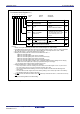
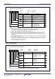
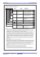
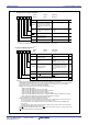
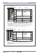
Figure 7.5 CM2 Register
b7 b6 b5 b4 b3 b2 b1 b0
RW
CM20
CM21
Oscillation Stop Detection Register
(1)
Symbol Address After Reset
CM2
000C
16
0X0000102
(11)
Bit Name
Function
Bit Symbol
System clock select bit 2
(2, 3, 6, 8, 11, 12 )
0: Oscillation stop, re-oscillation
detection function disabled
1: Oscillation stop, re-oscillation
detection function enabled
0: Main clock or PLL clock
1: On-chip oscillator clock
(On-chip oscillator oscillating)
Oscillation stop, re-
oscillation detection bit
(7, 9, 10, 11)
CM22
CM23
Oscillation stop, re-
oscillation detection flag
0: Main clock stop,or re-oscillation
not detected
1: Main clock stop,or re-oscillation
detected
0: Main clock oscillating
1: Main clock not oscillating
X
IN
monitor flag
(4)
CM27
0: Oscillation stop detection reset
1: Oscillation stop, re-oscillation
detection interrupt
Nothing is assigned. When write, set to 0. When read, its
content is undefined
Operation select bit
(when an oscillation stop,
re-oscillation is detected)
(11)
RW
RW
RW
RW
RO
(b6)
(5)
Reserved bit
(b5-b4)
Set to 0
RW
00
NOTES:
1. Write to this register after setting the PRC0 bit in the PRCR register to 1 (write enable).
2. When the CM20 bit is 1 (oscillation stop, re-oscillation detection function enabled), the CM27 bit is set to 1
(oscillation stop, re-oscillation detection interrupt), and the CPU clock source is the main clock, the CM21 bit is
automatically set to 1 (on-chip oscillator clock) if the main clock stop is detected.
3. If the CM20 bit is set to 1 and the CM23 bit is set to 1 (main clock not oscillating), do not set the CM21 bit to 0.
4. This flag is set to 1 when the main clock is detected to have stopped or when the main clock is detected
to have restarted oscillating. When this flag changes state from 0 to 1, an oscillation stop, reoscillation restart
detection interrupt is generated. Use this flag in an interrupt routine to discriminate the causes of interrupts
between the oscillation stop, reoscillation detection interrupts and the watchdog timer interrupt. The flag is
cleared to 0 by writing 0 by program. (Writing 1 has no effect. Nor is it cleared to 0 by an oscillation stop or an
oscillation restart detection interrupt request acknowledged.) If when the CM22 bit is set to 1 an oscillation
stoppage or an oscillation restart is detected, no oscillation stop, reoscillation restart detection interrupts are
generated.
5. Read the CM23 bit in an oscillation stop, re-oscillation detection interrupt handling routine to determine the
main clock status.
6. Effective when the CM07 bit in the CM0 register is set to 0.
7. When the PM21 bit in the PM2 register is 1 (clock modification disabled), writing to the CM20 bit has no effect.
8. When the CM20 bit is set to 1 (oscillation stop, re-oscillation detection function enabled), the CM27 bit is set 1
(oscillation stop, re-oscillation detection interrupt), and the CM11 bit is 1 (the CPU clock source is PLL clock),
the CM21 bit remains unchanged even when main clock stop is detected. If the CM22 bit is set to 0 under
these conditions, oscillation stop, re-oscillation detection interrupt occur at main clock stop detection; it is,
therefore, necessary to set the CM21 bit to 1 (on-chip oscillator clock) inside the interrupt routine.
9. Set the CM20 bit to 0 (disable) before entering stop mode. After exiting stop mode, set the CM20 bit back to 1
(enable).
10. Set the CM20 bit to 0 (disable) before setting the CM05 bit in the CM0 register.
11. Bits CM20, CM21 and CM27 do not change at oscillation stop detection reset.
12. When the CM21 bit is set to 0 (on-chip oscillator turned off) and the CM05 bit is set to 1 (main clock turned
off), the CM06 bit is fixed to 1 (divide-by-8 mode) and the CM15 bit is fixed to 1 (drive capability High).