
Datasheet


20. Flash Memory Version
puorG92/C61M
page 342
854fo7002,03.raM21.1.veR
2110-1010B90JER
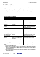
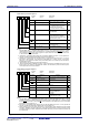
Figure 20.7 FMR4 Register
Flash Memory Control Register 4
Symbol
Address
After Reset
FMR4
01B3
16
01000000
2
b7 b6 b5 b4 b3 b2 b1 b0
Bit Symbol
Bit Name Function
Erase suspend
request bit
(2)
0: Erase restart
1: Suspend request
FMR41
0
Reserved bit
Set to 0
Erase suspend function
enable bit
(1)
0: Disabled
1: Enabled
Reserved bit
Set to 0
00
RW
RW
RW
RO
RW
FMR40
(b5-b2)
(b7)
RO
FMR46
00
Erase status
0: During auto-erase operation
1: Auto-erase stop
(erase suspend mode)
NOTES:
1. Set the FMR40 bit to 1 immediately after setting it first to 0. Do not generate any interrupt or DMA
transfer between setting the bit to 0 and setting it to 1. Set by program in space other than the flash
memory in EW mode 0.
2. The FMR41 bit is valid only when the FMR40 bit is set to 1. The FMR41 bit can be written only
between executing an erase command and completing erase (this bit is set to 0 other than the
above duration). The FMR41 bit can be set to 0 or 1 by program in EW mode 0. In EW mode 1, the
FMR41 bit is automatically set to 1 when the FMR40 bit is 1 and a maskable interrupt is generated
during erasing. The FMR41 bit cannot be set to 1 by program (it can be set to 0 by program).