
Datasheet


14. Serial I/O
puorG92/C61M
page 177
854fo7002,03.raM21.1.veR
2110-1010B90JER
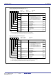
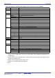
Figure 14.7 U0C1 to U2C1 Register, and PACR Register
UARTi Transmit/receive Control Register 1 (i=0, 1)
Symbol Address After Reset
U0C1, U1C1 03A5
16,03AD16 000000102
b7 b6 b5 b4 b3 b2 b1 b0
Bit Name
Bit
Symbol
RW
Function
TE
TI
RE
RI
Transmit enable bit
Receive enable bit
Receive complete flag
Transmit buffer
empty flag
0 : Transmission disabled
1 : Transmission enabled
0 : Data present in UiTB register
1 : No data present in UiTB register
0 : Reception disabled
1 : Reception enabled
0 : No data present in UiRB register
1 : Data present in UiRB register
Nothing is assigned.
If necessary, set to 0. When read, the content is 0
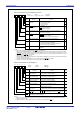
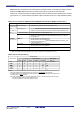
UART2 Transmit/receive Control Register 1
Symbol Address After Reset
U2C1 037D
16 000000102
b7 b6 b5 b4 b3 b2 b1 b0
Bit Name
Bit
Symbol
Function
TE
TI
RE
RI
Transmit enable bit
Receive enable bit
Receive complete flag
Transmit buffer
empty flag
0 : Transmission disabled
1 : Transmission enabled
0 : Reception disabled
1 : Reception enabled
U2IRS UART2 transmit interrupt
cause select bit
0 : Transmit buffer empty (TI = 1)
1 : Transmit is completed (TXEPT = 1)
U2RRM UART2 continuous
receive mode enable bit
0 : Continuous receive mode disabled
1 : Continuous receive mode enabled
Data logic select bit 0 : No reverse
1 : Reverse
U2LCH
U2ERE Error signal output
enable bit
0 : Output disabled
1 : Output enabled
RW
RW
RO
RO
RW
RW
RW
RW
RW
RW
RW
RO
RO
(b7-b4)
0 : Data present in U2TB register
1 : No data present in U2TB register
0 : No data present in U2RB register
1 : Data present in U2RB register
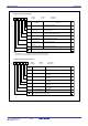
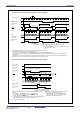
Pin Assignment Control Register
(1)
Symbpl Address After Reset
PACR 025D
16
00
16
Bit Name FunctionBit Symbol
RW
b7 b6 b5 b4 b3 b2 b1 b0
Pin enabling bit
RW
(b6-b3)
010 : 64 pin
011 : 80 pin
All other values are reserved. Do
not use.
PACR0
PACR1
PACR2
RW
RW
Reserved bits
U1MAP UART1 pin remapping bit
UART1 pins assigned to
0 : P6
7 to P6
4
1 : P7
3
to P7
0
RW
NOTE:
1. Set the PACR register by the next instruction after setting the PRC2 bit in the PRCR register to 1(write enable).
Nothing is assigned.
If necessary, set to 0. When
read, the content is 0