
Datasheet


12. Timer (Three-phase Motor Control Timer Function)
puorG92/C61M
page 139
854fo7002,03.raM21.1.veR
2110-1010B90JER
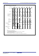
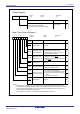
Figure 12.38 PFCR Register, and TPRC Register
Port Function
C
ontrol Re
g
ister
(1)
Symbol Address After Reset
PFCR 0358
16 0011 11112
RW
RW
RW
RWBit Name FunctionBit Symbol
PFC0
PFC1
PFC2
Port P80 output
function select bit
NOTE:
1. This register is valid only when the INVC03 bit in the INVC0 register is 1 (Three-phase motor control
timer.
(b7-b6)
RW
PFC3
Nothing is assigned. If necessary, set to 0. When read,
the contents are 0
0: Input/Output port P8
0
1: Three-phase PWM output
(U phase output)
PFC4
PFC5
RW
RW
Port P81 output
function select bit
Port P7
2 output
function select bit
Port P7
3 output
function select bit
Port P7
4 output
function select bit
Port P7
5 output
function select bit
0: Input/Output port P8
1
1: Three-phase PWM output
(U phase output)
0: Input/Output port P7
2
1: Three-phase PWM output
(V phase output)
0: Input/Output port P7
3
1: Three-phase PWM output
(V phase output)
0: Input/Output port P7
4
1: Three-phase PWM output
(W phase output)
0: Input/Output port P7
5
1: Three-phase PWM output
(W phase output)
b
7
b5
b
4
b3
b
2b1b0
Three-phase Protect
C
ontrol Re
g
ister
Symbol Address After Reset
TPRC 025A
16
00
16
RW
RWBit Name FunctionBit Symbol
TPRC0
Three-phase
protect control bit
(b7-b1)
Nothing is assigned. If necessary, set to 0. When read,
the contents are 0
Enable write to PFCR register
0: Write protected
1: Write enabled
b
7
b3
b
2b1b0