
Datasheet

12. Timer (Three-phase Motor Control Timer Function)
puorG92/C61M
page 130
854fo7002,03.raM21.1.veR
2110-1010B90JER
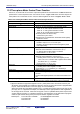
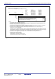
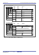
Figure 12.29
TA1, TA2, TA4, TA11, TA21, and TA41 Registers
Symbol Address After reset
TA1 0389
16-038816
Undefined
TA2 038B
16-038A16
Undefined
TA4 038F
16-038E16 Undefined
TA11
(6,7)
034316-034216 Undefined
TA21
(6,7)
034516-034416 Undefined
TA41
(6,7)
034716-034616 Undefined
b7 b0 b7
b0
(b15) (
b8)
RW
Assuming the set value = n, upon a start trigger the timer
starts counting the count source and stops after counting
it n times. The positive and negative phases change at
the same time timer A, A2 or A4 stops.
Function
Setting Range
Timer Ai, Ai-1 Register (i=1, 2, 4)
(1, 2, 3, 4, 5)
NOTES:
1. The register must be accessed in 16 bit units.
2. When the timer Ai register is set to 0000
16, the counter does not operate and a timer Ai interrupt does not occur.
3. Use MOV instruction to write to these registers.
4. If the INV15 bit is 0 (dead time timer enable), the positive or negative phase whichever is going from an inactive
to an active level changes at the same time the dead time timer stops.
5. If the INV11 bit is 0 (three-phase mode 0), the TAi register value is transferred to the reload register by
a timer Ai (i = 1, 2 or 4) start trigger.
If the INV11 bit is 1 (three-phase mode 1), the TAi1 register value is transferred to the reload register by a timer Ai
start trigger first and then the TAi register value is transferred to the reload register by the next timer Ai start trigger.
Thereafter, the TAi1 register and TAi register values are transferred to the reload register alternately.
6. Do not write to TAi1 registers synchronously with a timer B2 underflow In three-phase mode 1.
7. Write to the TAi1 register as follows:
(1) Write a value to the TAi1 register
(2) Wait for one cycle of timer Ai count source.
(3) Write the same value to the TAi1 register again.
WO
0000
16 to FFFF16