
Datasheet

12. Timer (Three-phase Motor Control Timer Function)
puorG92/C61M
page 128
854fo7002,03.raM21.1.veR
2110-1010B90JER
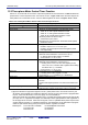
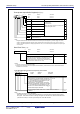
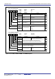
Figure 12.27 INVC1 Register
Three-phase PWM Control Register 1
(1)
Symbol Address After Reset
INVC1 0349
16
00
16
b7 b6 b5 b4 b3 b2 b1 b0
Timer A1, A2, A4 start
trigger signal select bit
INV10
Bit Symbol Bit Name Function
RW
INV11
Timer A1-1, A2-1, A4-1
control bit
INV12
Dead time timer count
source select bit
INV14 Output polarity control bit
(b7)
Reserved bit
INV16
INV15 Dead time invalid bit
INV13 Carrier wave detect flag
(5)
0: Timer B2 underflow
1: Timer B2 underflow and write to the
TB2 register
(2)
0: Three-phase mode 0
1: Three-phase mode 1
0: f
1
or f
2
1: f
1
divided by 2 or f
2
divided by 2
0: Timer Reload control signal is set to 0
1: Timer Reload control signal is set to 1
0 : Output waveform “L” active
1 : Output waveform “H” active
0: Dead time timer enabled
1: Dead time timer disabled
Set to 0
RW
RW
RW
RW
RW
RW
RW
RO
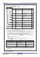
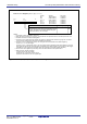
(3)
Item
Mode
TA11, TA21, TA41 registers
INV00 bit, INV01 bit
INV13 bit
INV11=0
Three-phase mode 1
Three-phase mode 0
Not Used
Has no effect. ICTB2 counted every time
timer B2 underflows regardless of
whether bits INV00 and INV01 are set
Has no effect
INV11=1
Used
Effect
Effective when INV11 bit is 1 and
INV06 bit is 0
(4)
0
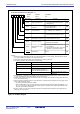
4. If the INV06 bit is 1 (sawtooth wave modulation mode), set this bit to 0 (three-phase mode 0). Also, if the INV11 bit is
0, set the PWCON bit to 0 (timer B2 reloaded by a timer B2 underflow).
5. The INV13 bit is effective only when the INV06 bit is set to 0 (triangular wave modulation mode) and the INV11 bit is
set to 1 (three-phase mode 1).
6. If all of the following conditions hold true, set the INV16 bit to 1 (dead time timer triggered by the rising edge of three-
phase output shift register output)
• The INV15 bit is 0 (dead time timer enabled)
• When the INV03 bit is set to 1 (three-phase motor control timer output enabled), the Dij bit and DiBj bit (i:U, V, or
W, j: 0 to 1) have always different values (the positive-phase and negative-phase always output different levels
during the period other than dead time).
Conversely, if either one of the above conditions holds false, set the INV16 bit to 0 (dead time timer triggered by the
falling edge of one-shot pulse).
NOTES:
1. Write to this register after setting the PRC1 bit in the PRCR register to 1 (write enable). Note also that this register
can only be rewritten when timers A1, A2, A4 and B2 are idle.
2. A start trigger is generated by writing to the TB2 register only while timer B2 stops.
3. The effects of the INV11 bit are described in the table below.
0: Falling edge of timer A4, A1 or A2
one-shot pulse
1: Rising edge of three-phase output shift
register (U, V or W phase) output
(6)
Dead time timer trigger
select bit