
Datasheet


9. Interrupts
puorG92/C61M
page 76
854fo7002,03.raM21.1.veR
2110-1010B90JER
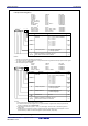
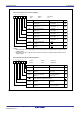
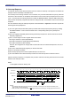
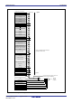
Figure 9.3 Interrupt Control Registers
C01WKIC, C0RECIC, C0TRMIC, ICOC0IC, ICOC1IC, IICIC, BTIC, SCLDAIC, BCNIC, DM0IC, DM1IC, C01ERRIC, ADIC, KUPIC, S0TIC to S2TIC, S0RIC to S2RIC, TA0IC to TA4IC, TB0IC to TB2IC, INT3IC, S4IC, INT5IC, S31C, INT4IC, INT0IC to INT2IC Registers
Symbol Address After reset
INT3IC 0044
16
XX00X000
2
S4IC, INT5IC 0048
16
XX00X000
2
S3IC, INT4IC 0049
16
XX00X000
2
INT0IC to INT2IC 005D
16
to 005F
16
XX00X000
2
Bit Name FunctionBit Symbol
b
b
4
b3
b
2b1b0
ILVL0
IR
POL
Interrupt priority level
select bit
Interrupt request bit
Polarity select bit
Reserved bit
0: Interrupt not requested
1: Interrupt requested
0: Selects falling edge
(3, 4)
1: Selects rising edge
Set to 0
ILVL1
ILVL2
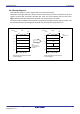
Interrupt Control Register
(2)
b
b
4
b3
b
2b1b0
Bit Name FunctionBit Symbol
RW
Symbol Address After reset
C01WKIC 0041
16 XXXXX000
2
C0RECIC 0042
16
XXXXX000
2
C0TRMIC 004316 XXXXX000
2
ICOC0IC 0045
16
XXXXX000
2
ICOC1IC, IICIC
(3)
0046
16
XXXXX000
2
BTIC, SCLDAIC
(3)
004716 XXXXX000
2
BCNIC 004A
16
XXXXX000
2
DM0IC, DM1IC 004B
16
, 004C
16
XXXXX000
2
C01ERRIC 004D
16
XXXXX000
2
ADIC, KUPIC
(3)
004E16 XXXXX000
2
S0TIC to S2TIC 005116, 005316, 004F16 XXXXX000
2
S0RIC to S2RIC 005216, 005416, 005016 XXXXX000
2
TA0IC to TA4IC 005516 to 005916 XXXXX000
2
TB0IC to TB2IC 005A16 to 005C16 XXXXX000
2
ILVL0
IR
Interrupt priority level
select bit
Interrupt request bit 0: Interrupt not requested
1: Interrupt requested
ILVL1
ILVL2
0 0 0 : Level 0 (interrupt disabled)
0 0 1 : Level 1
0 1 0 : Level 2
0 1 1 : Level 3
1 0 0 : Level 4
1 0 1 : Level 5
1 1 0 : Level 6
1 1 1 : Level 7
b2 b1 b0
0 0 0 : Level 0 (interrupt disabled)
0 0 1 : Level 1
0 1 0 : Level 2
0 1 1 : Level 3
1 0 0 : Level 4
1 0 1 : Level 5
1 1 0 : Level 6
1 1 1 : Level 7
b2 b1 b0
0
RW
RW
RW
RW
(1)
(b7-b4)
RW
RW
RW
RW
RW
RW
(b7-b6)
(b5)
RW
(1)
NOTES:
1. This bit can only be reset by writing 0 (Do not write 1).
2. To rewrite the interrupt control registers, do so at a point that does not generate the interrupt request for that register.
For details, refer to 22. 4 Interrupts.
3. Use the IFSR2A register to select.
NOTES:
1. This bit can only be reset by writing 0 (Do not write 1).
2. To rewrite the interrupt control register, do so at a point that does not generate the interrupt request for that
register. For details, refer to 22.4 Interrupts.
3. If the IFSRi bit in the IFSR register (i = 0 to 5) is 1 (both edges), set the POL bit in the INTiIC register to 0
(falling edge).
4. Set the POL bit in register S3IC or S4IC to 0 (falling edge) when the IFSR6 bit in the IFSR register is set to 0
(SI/O3 selected) or IFSR7 bit in the IFSR register to 0 (SI/O4 selected), respectively.
Nothing is assigned. If necessary, set to 0.
When read, the contents are undefined
Nothing is assigned. If necessary, set to 0.
When read, the contents are undefined