REJ10J1459-0200(T) M3028BT-EPB User's Manual Emulation Probe for M16C/Tiny Series Rev.2.00 Sep.
Keep safety first in your circuit designs! 1. Renesas Technology Corp. puts the maximum effort into making semiconductor products better and more reliable, but there is always the possibility that trouble may occur with them. Trouble with semiconductors may lead to personal injury, fire or property damage.
M3028BT-EPB User’s Manual Preface Preface The M3028BT-EPB is an emulation probe for M16C/Tiny Series MCUs. The M3028BT-EPB is used by connecting to the PC7501 emulator main unit. This user's manual mainly describes specifications of the M3028BT-EPB emulation probe and how to setup it. For details on the following products, which are used with the M3028BT-EPB, refer to each product's user's manual. All the components of this product are shown in "1.1 Package Components" (page 13).
M3028BT-EPB User’s Manual Important Important Before using this product, be sure to read this user’s manual carefully. Keep this user’s manual, and refer to this when you have questions about this product. Emulator: The emulator in this document refers to the following products that are manufactured by Renesas Technology Corp.
M3028BT-EPB User’s Manual Important Usage restrictions: This emulator has been developed as a means of supporting system development by users. Therefore, do not use it as a device used for equipment-embedded applications.
M3028BT-EPB User’s Manual Precautions for Safety Precautions for Safety Definitions of Signal Words In both the user’s manual and on the product itself, several icons are used to insure proper handling of this product and also to prevent injuries to you or other persons, or damage to your properties. This chapter describes the precautions which should be taken in order to use this product safely and properly. Be sure to read this chapter before using this product.
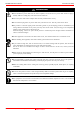
M3028BT-EPB User’s Manual Precautions for Safety WARNING Warnings for AC Power Supply: z If the attached AC power cable does not fit the receptacle, do not alter the AC power cable and do not plug it forcibly. Failure to comply may cause electric shock and/or fire. z Use an AC power cable which complies with the safety standard of the country. z Do not touch the plug of the AC power cable when your hands are wet. This may cause electric shock. z This product is connected signal ground with frame ground.
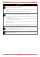
M3028BT-EPB User’s Manual Precautions for Safety CAUTION Cautions to Be Taken for Turning On the Power: z Turn ON the power of the emulator and user system as simultaneously as possible. Turn OFF the power of the emulator and user system as simultaneously as possible. z Do not leave either the emulator or user system powered on, because of leakage current the internal circuits may be damaged. z When turning ON the power again after shutting OFF the power, wait about 10 seconds.
M3028BT-EPB User’s Manual Contents Contents Page Preface..........................................................................................................................................................................3 Important.......................................................................................................................................................................4 Precautions for Safety .................................................................................
M3028BT-EPB User’s Manual Contents Page 4. Hardware Specifications .........................................................................................................................................65 4.1 Target MCU Specifications............................................................................................................................65 4.2 Differences between the Actual MCU and Emulator.....................................................................................66 4.
M3028BT-EPB User’s Manual User Registration User Registration When you have purchased the emulator presented in this user's manual, please be sure to register it. As the H/W Tool Customer Registration Sheet is included with this manual, fill it in and FAX it to your local distributor or email the same contents to the following address. If you register it by email, you can use a text format for user registration created when installing the software in the following folder.
M3028BT-EPB User’s Manual Terminology Terminology Some specific words used in this user's manual are defined as follows: Emulator system This means an emulator system built around the PC7501 emulator. The PC7501 emulator system is configured with an emulator main unit, emulation probe, host machine and integrated development environment High-performance Embedded Workshop. Emulator main unit (Hereafter PC7501) This means an emulator main unit for M16C Family MCUs.
M3028BT-EPB User’s Manual 1. Outline 1. Outline This chapter describes the package components, the system configuration and the preparation for using this product for the first time. 1.1 Package Components The M3028BT-EPB package consists of the following items. When unpacking it, check to see if your M3028BT-EPB contains all of these items. Table 1.
M3028BT-EPB User’s Manual 1. Outline 1.2 Other Tool Products Required for Development To bring forward programs development on the M16C/Tiny Series MCUs, the products listed below are necessary in addition to those contained package above. Get them separately. Table 1.2 Other tool products required for development Product Emulator main unit Emulator debugger Product name PC7501 M16C R8C PC7501 Emulator Debugger M3T-PD30F Package converter board 42-pin 0.
M3028BT-EPB User’s Manual 1. Outline 1.3 System Configuration 1.3.1 System Configuration Figure 1.1 shows a configuration of the M3028BT-EPB system. Host machine interface (LPT parallel, USB or LAN) (4) Host machine (3) Emulator main unit PC7501 (1) Emulation probe M3028BT-EPB (2) Package converter board M30290T-80FPD etc. (5) User system Figure 1.
M3028BT-EPB User’s Manual 1. Outline 1.3.2 Names and Functions of the PC7501 Upper Panel LEDs Figure 1.2 shows the names of the LEDs on the upper panel of the emulator. Figure 1.2 Names of the LEDs on the upper panel of the PC7501 (1) System Status LEDs The system status LEDs indicate the emulator PC7501's power supply, firmware operating status, etc. Table 1.3 lists the definition of each system status LED. Table 1.
M3028BT-EPB User’s Manual 1. Outline (2) Target Status LEDs The target status LEDs indicate the target MCU's operating status and target board's power supply. Table 1.4 lists the definition of each target status LED. Table 1.4 Definitions of the target status LEDs Name POWER CLOCK RESET RUN WARNING Status ON OFF ON OFF ON OFF ON OFF ON OFF Meaning Power is supplied to the user system. Power is not supplied to the user system. Target MCU clock is oscillating. Target MCU clock is not oscillating.
M3028BT-EPB User’s Manual 1. Outline 1.4 Specifications Tables 1.5 lists the specifications of the M3028BT-EPB. Table 1.5 M3028BT-EPB specifications (1/2) Emulator Applicable MCU Evaluation MCU PC7501 M16C/Tiny Series MCUs M30290FCWP ROM: 128KB + 4KB, RAM: 12KB Usable MCU mode Single-chip mode Max. ROM/RAM capacity (1) Internal flash ROM: 128KB + 4KB 0F000h--0FFFFh, E0000h--FFFFFh, for the maximum operating frequency, refer to *1.
M3028BT-EPB User’s Manual 1. Outline 1.5 Operating Environment Be sure to use this emulator with the operating environmental of the emulator and host machine listed in Tables 1.6 and 1.7. Table 1.6 Operating environmental conditions Item Operating temperature Storage temperature Description 5 to 35°C (no dew) -10 to 60°C (no dew) Table 1.
M3028BT-EPB User’s Manual 2. Setup 2. Setup This chapter describes the preparation for using this product, the procedure for starting up the emulator and how to change settings. 2.1 Flowchart of Starting Up the Emulator The procedure for starting up the emulator is shown in Figure 2.1. For details, refer to each section hereafter. And, when the emulator does not start up normally, refer to “5. Troubleshooting” (page 78). Check the package components. Refer to “1.1 Package Components (page 13).
M3028BT-EPB User’s Manual 2. Setup 2.2 Installing the Emulator Debugger If the OS used in your host machine is Windows XP or 2000, this installation must be executed by a user with administrator rights. Be aware that users without administrator rights cannot complete the installation. Install the emulator debugger (M16C R8C PC7501 Emulator Debugger) following the procedure described below. (1) Downloading the emulator debugger Download the latest M16C R8C PC7501 emulator debugger from the URL below.
M3028BT-EPB User’s Manual 2. Setup 2.3 Connecting the Host Machine When connecting the emulator PC7501 to a host machine, you can choose your desired interface from LPT parallel interface, USB interface and LAN interface. Use the interface selection switch on the emulator PC7501's rear panel to specify your desired interface. Figure 2.2 shows the outline to connect each interface cable. Figure 2.2 Outline for interface cable connections REJ10J1459-0200 Rev.2.
M3028BT-EPB User’s Manual 2. Setup 2.4 Connecting the PC7501 Figure 2.3 shows how to connect the PC7501 and the emulation probe. M3T-FLX160-EPB Emulation probe Figure 2.3 Connecting the PC7501 and emulation probe CAUTION Notes on Connecting the PC7501: z When connecting the emulation probe, be sure to hold the both sides of the emulation probe horizontally and insert it directly. z Always shut OFF power before connecting the emulation probe. Otherwise, internal circuits may be damaged.
M3028BT-EPB User’s Manual 2. Setup 2.5 Connecting the Power Supply for the Emulator The power is supplied from AC adapter to the emulator PC7501. Here following explains how to connect the AC adapter. (1) (2) (3) (4) Turn OFF the power to the PC7501. Connect the DC cable of AC adapter to the PC7501. Connect the AC power cable to the AC adapter. Connect the AC power cable to the receptacle. CAUTION Notes on AC Adapter: z Use only the AC adapter included in PC7501 package.
M3028BT-EPB User’s Manual 2. Setup 2.6 Turning ON the Power 2.6.1 Checking the Connections of the Emulator System Before turning the power ON, check the connection of the interface cable with host machine, PC7501, emulation probe, and user system. 2.6.2 Turning ON/OFF the Power z Turn ON the power of the emulator and user system as simultaneously as possible. z Turn OFF the power of the emulator and user system as simultaneously as possible.
M3028BT-EPB User’s Manual 2. Setup 2.6.3 LED Display When the PC7501 Starts Up Normally Figure 2.4 shows upper panel LED lighting status when the emulator started up properly. Check it when starting up the emulator system. - If this LED does not light, check the voltage of the user system . - Check that power is supplied to all the power pins . - When the user system is not connected , this LED does not light. POWER POWER POWER - When this LED lights, check the reset pin of the user system.
M3028BT-EPB User’s Manual 2. Setup 2.7 Downloading Firmware 2.7.1 When It is Necessary to Download Firmware It is necessary to download the firmware in the cases listed below. Normally, the following are automatically detected when the emulator debugger is started up, and the firmware is downloaded.
M3028BT-EPB User’s Manual 2. Setup 2.8 Self-check 2.8.1 Self-check Procedure The self-check is a function to check the memory etc. mounted in the emulator. To run the self-check of the emulator, do so as explained here below. While the self-check is in progress, the LEDs will change as shown in Figure 2.6. In case of ERRORs 1 to 4, because the target status LEDs will change depending on errors, check the system status LEDs. (1) If the user system is connected, disconnect it.
M3028BT-EPB User’s Manual 2. Setup 2.8.2 If an Error is Detected in the Self-check If the self-check does not result normally (ERROR 1 to ERROR 4 in Figure 2.6), check the following. (1) Recheck the connection of the emulation probe and PC7501. (2) Redownload the proper firmware. IMPORTANT Notes on the Self-check: z Disconnect the user system before execute the self-check. z If the self-check does not result normally (excluding user system errors), the emulation probe may be damaged.
M3028BT-EPB User’s Manual 2. Setup 2.9 Connecting the User System There are eight ways available to connect the emulation probe to user systems as shown in Figure 2.7. Emulation probe M3028BT-EPB 42-pin 0.8mm pitch M30263T-42SSB SSOP 48-pin 0.5mm pitch M30260T-48FPD LQFP 64-pin 0.5mm pitch M30291T-64FPD LQFP YQ-GUIDE (x4) *2 Socket frame (x2) *1 M3T-SSOP42B-450 *1 YQ-GUIDE (x4) *3 YQPACK048SD *2 YQPACK064SD *3 NQPACK048SD *2 NQPACK064SD-ND *3 80-pin 0.5mm pitch M30290T-80FPD LQFP 85-pin 0.
M3028BT-EPB User’s Manual 2. Setup 2.9.1 Connecting to a 42-pin 0.8mm pitch Foot Pattern Here following is a procedure of connecting to a 42-pin 0.8mm pitch foot pattern on the user system using the M30263T42SSB (included with the M3028BT-EPB-1). For details on the M30263T-42SSB, refer to its user's manual. (1) (2) (3) (4) Mount the socket main unit included with the M30263T-42SSB to the user system. Attach the M3T-SSOP42B-450 included with the M30263T-42SSB and the socket frame to the socket main unit.
M3028BT-EPB User’s Manual 2. Setup 2.9.2 Connecting to a 48-pin 0.5mm pitch Foot Pattern Here following is a procedure of connecting to a 48-pin 0.5mm pitch foot pattern on the user system using the M30260T48FPD (included with the M3028BT-EPB-2). For details on the M30260T-48FPD, refer to its user's manual. (1) Mount the NQPACK048SD included with the M30260T-48FPD to the user system. (2) Attach the YQPACK048SD included with the M30260T-48FPD to the NQPACK048SD and secure it with the YQGUIDE's.
M3028BT-EPB User’s Manual 2. Setup 2.9.3 Connecting to a 64-pin 0.5mm pitch Foot Pattern Here following is a procedure of connecting to a 64-pin 0.5mm pitch foot pattern on the user system using the M30291T64FPD (included with the M3028BT-EPB-3). For details on the M30291T-64FPD, refer to its user's manual. (1) Mount the NQPACK064SD-ND included with the M30291T-64FPD to the user system. (2) Attach the YQPACK064SD included with the M30291T-64FPD to the NQPACK064SD-ND and secure it with the YQGUIDE's.
M3028BT-EPB User’s Manual 2. Setup 2.9.4 Connecting to an 80-pin 0.5mm pitch Foot Pattern Here following is a procedure of connecting to an 80-pin 0.5mm pitch foot pattern on the user system using the M30290T80FPD (included with the M3028BT-EPB-4). For details on the M30290T-80FPD, refer to its user's manual. (1) Mount the NQPACK080SD-ND included with the M30290T-80FPD to the user system. (2) Attach the YQPACK080SD included with the M30290T-80FPD to the NQPACK080SD-ND and secure it with the YQGUIDE's.
M3028BT-EPB User’s Manual 2. Setup 2.9.5 Connecting to a 85-pin 0.65mm pitch Foot Pattern Here following is a procedure of connecting to an 85-pin 0.65mm pitch foot pattern on the user system with the M30280T85LGF (included with the M3028BT-EPB-5), and here following is its procedure. For details on the M30280T-85LGF, refer to its user's manual. (1) Attach the CSSOCKET085B1007RE01 included with the M30280T-85LGF to the user system.
M3028BT-EPB User’s Manual 2. Setup 2.10 A/D Conversion Bypass Capacitors There is a foot pattern on the M3028BT-EPBM board for mounting bypass capacitors for the A/D conversion circuit near the MCU. Mount suitable bypass capacitors as occasion demands. Figure 2.13 shows where they are installed and the configuration of this product. Component side of the M3028BT-EPBM M30290T-EPBM REV.C C1 AV CC -AV SS bypass capacitor AV CC C2 AV SS V REF -AV SS bypass capacitor V REF AV SS Figure 2.
M3028BT-EPB User’s Manual 2. Setup 2.11 Selecting Clock Supply 2.11.1 Selecting Clock Supply You can choose a clock supplied to the evaluation MCU by the Emulator tab in the Init dialog box of the emulator debugger. Table 2.1 shows the clocks and their initial settings. Table 2.
M3028BT-EPB User’s Manual 2. Setup (2) Replacing an Oscillator Circuit Board 1. Remove the four screws of both sides of this product and lift off the upper cover (see Figure 2.14). Figure 2.14 Removing the upper cover REJ10J1459-0200 Rev.2.
M3028BT-EPB User’s Manual 2. Setup 2. Unscrew the screw of the oscillator circuit board of the PC7501 and replace it (see Figure 2.15). The oscillator circuit board of the PC7501 is in the lower right corner of the board. Unscrew the screw securing the oscillator circuit board. Lift off the oscillator circuit board. Attach another oscillator circuit board to the connector. Secure the new oscillator circuit board with the screw. Figure 2.15 Replacing oscillator circuit boards 3.
M3028BT-EPB User’s Manual 2. Setup (3) Using the Oscillator Circuit Bare Board To use this product at a frequency you like, build a desired oscillator circuit on the included OSC-2 oscillator circuit bare board. Figure 2.16 shows an external view of the OSC-2 oscillator circuit bare board and the connector pin locations. Figure 2.17 shows the circuitry of the oscillator circuit bare board OSC-2. Use the number of oscillator circuits recommended by the oscillator manufacturer.
M3028BT-EPB User’s Manual 2. Setup 2.11.3 Using the Oscillator Circuit on the User System To operate this product with an oscillator circuit of the user system, input the oscillator output at 50% duty (within the operating range of the evaluation MCU) into pin XIN as shown in Figure 2.18. Pin XOUT should be open. Choose "External" in the emulator debugger to use this clock. Figure 2.18 External oscillator circuit In the oscillator circuit shown in Figure 2.
M3028BT-EPB User’s Manual 3. Usage (Emulator Debugger) 3. Usage (Emulator Debugger) This chapter describes how to start up the emulator debugger and how to use the major windows. 3.1 Starting Up the Emulator Debugger When debugging the completed programs, switch the session. The session can be changed by the drop down list of the tool bar shown below.
M3028BT-EPB User’s Manual 3. Usage (Emulator Debugger) 2. Specifying the communication interface Specifying the communication interface (LPT communication) - For selecting the LPT communication, click the radio button “LPT” of the MCU tab. - For the Type area, specify the LPT interface communication mode to be used. When you use the emulator debugger for the first time, select “AUTO”. - Specify the I/O address of the parallel port at the I/O address area.
M3028BT-EPB User’s Manual 3. Usage (Emulator Debugger) 3. Executing the self-check Executing the self-check Enable this function when you want the emulator to be selfchecked at startup. Be sure to select the check box only when you want the emulator to be self-checked at startup.
M3028BT-EPB User’s Manual 3. Usage (Emulator Debugger) (2) Debugging Information tab Specifying the compiler used and the object format Specify the compiler you are using and the format of the object file output by the compiler. - Compiler Select the compiler you are using. (By default, the C compiler from Renesas is selected.) - Object Format Select the format of the object file that is output by the compiler you are using.
M3028BT-EPB User’s Manual 3. Usage (Emulator Debugger) (4) Script tab Automatically executing a script command To automatically execute a script command when starting up the debugger, click the “Refer...” button and specify the script file to be executed. Clicking the “Refer...” button brings up a file selection dialog box. The script file you have selected is displayed in the Init File: section of the dialog box shown here.
M3028BT-EPB User’s Manual 3. Usage (Emulator Debugger) 3.1.2 MCU Setting Dialog Box MCU setting dialog box sets the information of the user system. It will be displayed after closing the Init dialog box. When the tab settings of (1) to (3) have been finished, click “OK”. (1) MCU tab 1. MCU setting Specifying the processor mode Select the appropriate processor mode that suits your system.
M3028BT-EPB User’s Manual 3. Usage (Emulator Debugger) 2. Option Setting the debug options Specify whether you want to use the internal flash ROM or the MCU or not. Check the box when not downloading the program to the internal flash ROM of the MCU. Initially, this option is deselected. If this box is checked, the number of write/erase cycles of the internal flash ROM will be unlimited, and working efficiency (downloading, software break, etc.
M3028BT-EPB User’s Manual 3. Usage (Emulator Debugger) (2) MAP tab Emulation Memory Allocation as Expansion Area With this product, setting of the MAP tab is not required. (3) Flash Clear tab Setting to clear the MCU’s internal flash ROM Specify whether or not you want the MCU’s internal flash ROM to be cleared when downloading the user program or data. (When cleared, the content of the flash ROM is initialized to 0xFF.) The MCU’s internal flash ROM is listed in block units.
M3028BT-EPB User’s Manual 3. Usage (Emulator Debugger) 3.1.3 Checking Connections of the Emulator System Checking connections of the emulator system When the emulator debugger is connected correctly to the emulator after you have finished setting up the Init dialog box and the MCU Setting dialog box, you will see a message “Connected” displayed on the “Debug” tab of the Output window. REJ10J1459-0200 Rev.2.
M3028BT-EPB User’s Manual 3. Usage (Emulator Debugger) 3.2 Program Window (1) Downloading the program 1. Downloading from the work space window Downloading the program Download the object program you want to debug. Select Download from “xxx.x30” of “Download module”. Or you can select “Download module” from the “Debug” menu for the same effect. 2.
M3028BT-EPB User’s Manual 3. Usage (Emulator Debugger) (2) Program execution 1 Resetting the user program CPU reset Resets the target MCU. Or you can select “CPU Reset” from “Debug" menu for the same effect. 2 Executing the user program (Go) Go Runs the program beginning with the current PC position. Or you can select “Go” from “Debug" menu for the same effect. 3 Executing the user program (Go Free) Go Free Runs the program beginning with the current PC position.
M3028BT-EPB User’s Manual 3. Usage (Emulator Debugger) (3) Setting breakpoints 1. Screen after breakpoint setup Breakpoint setup screen There are three types of breakpoints as described below. - Address match breakpoint (A) This breakpoint can be set only when you check “Enable the Address Match Interrupt Break Function.” on the MCU tab of the Init dialog box. A breakpoint can be set or cleared by double-clicking in the address match breakpoint display area in the editor (source) window.
M3028BT-EPB User’s Manual 3. Usage (Emulator Debugger) (4) Executing up to the cursor position (Come command) 1. Specifying the Come command Setup procedure for executing COME command (1) Click the line in the program display area at which you want the program to execute. (2) Click the Come button. 2. After the Come command has finished The cursor stops in the position where the come command was executed. The statement specified with the come command is not executed. REJ10J1459-0200 Rev.2.
M3028BT-EPB User’s Manual 3. Usage (Emulator Debugger) 3.3 Hardware Breakpoint Setting Window (1) Breakpoint setup dialog box 1. Opening the hardware breakpoint setup dialog box Hardware Break Point Clicking this button opens the hardware breakpoint setup dialog box. 2. Hardware Break Point Setting Window in initial state H/W Break Points Setting Window in initial state Select the “Enable H/W Break” check box, and this break function will be enabled, allowing you to set hardware breakpoints.
M3028BT-EPB User’s Manual 3. Usage (Emulator Debugger) 3. Opening the break event setting dialog box Specifying the event type Select the event type that you want to set from the dropdown list. - FETCH Detects an instruction prefetch. - DATA ACCESS Detects a memory access. - BIT SYMBOL Detects a bit access. - INTERRUPT Detects an interrupt occurrence or interrupt termination. - TRIGGER Detects a signal from the external trace signal input cable. (2) When FETCH is selected 1.
M3028BT-EPB User’s Manual 3. Usage (Emulator Debugger) (3) When DATA ACCESS is selected 1. Window for setting the address Setting the address You can set eight conditions, e.g., a specified address, a specified address range, etc. 2. Window for setting data Setting data You can set eight conditions, e.g., a specified data, a specified data range, etc. Setting the access condition You can set three conditions, e.g., read, write, and read/write.
M3028BT-EPB User’s Manual 3. Usage (Emulator Debugger) 3. Example Data Settings Event setting for even-address word access Setting a break event STE.W A0,20E8h(A0=5423h) A1 High-order and low-order data effective Event setting for odd-address word access STE.
M3028BT-EPB User’s Manual 3. Usage (Emulator Debugger) (4) Setting the combinatorial event condition 1. Window for setting the combinatorial event condition Setting the combinatorial event condition There are following four conditions that you can choose for the combinatorial events. - AND The program breaks when all of the specified events occur. - AND (Same Time) The program breaks when the specified events occur at the same time. - OR The program breaks when one of the specified events occurs.
M3028BT-EPB User’s Manual 3. Usage (Emulator Debugger) 3.4 Trace Window The Trace Window is used to display the results of real-time trace measurement. (1) Trace window 1. Opening the trace window Trace window Clicking this button opens the trace window. Or you can select “Trace” from “Trace” of “Display” menu for the same effect. 2. Trace window Trace window The trace window is used to show the results of real-time trace measurements.
M3028BT-EPB User’s Manual 3. Usage (Emulator Debugger) 3. Trace window (bus display) Explanation of the trace window (bus display) The following explains the displayed contents, from left to right. - Cycle Shows trace cycles. Double-click here to bring up a dialog box to change the displayed cycle. - Label Shows labels corresponding to address bus information. Double-click here to bring up a dialog box to search for addresses. - Address Shows the status of the address bus.
M3028BT-EPB User’s Manual 3. Usage (Emulator Debugger) (2) Suspending and resuming trace measurement 1. Suspending trace measurement Stop Click this toolbar button to suspend the trace measurement in progress. 2. Resuming trace measurement Re-Start Click this toolbar button to resume the trace measurement in progress. (3) Trace point setup dialog box 1. Opening the trace point setup dialog box Trace Point Clicking this toolbar button opens the trace point setting window. REJ10J1459-0200 Rev.2.
M3028BT-EPB User’s Manual 3. Usage (Emulator Debugger) 2. Trace Point Setting Window in initial state Trace Point Setting Window in initial state You can set events in the same way as for the hardware breakpoints. Specifying a trace range You can specify a trace range for the trace event. - Break 256K cycles of instruction execution before the user program stopped is recorded. - Before 256K cycles of instruction execution before a trace point condition was met is recorded.
M3028BT-EPB User’s Manual 3. Usage (Emulator Debugger) 3.5 RAM Monitor Window This function allows you to inspect changes of memory contents without impairing the realtime capability of target program execution. The PC7501 emulator system has 4 Kbytes of RAM monitor area which can be located in any contiguous address location or in 16 separate blocks comprised of 256 bytes each. (1) RAM monitor window 1. Opening the RAM monitor window RAM monitor Clicking this button opens the RAM monitor window. 2.
M3028BT-EPB User’s Manual 4. Hardware Specifications 4. Hardware Specifications This chapter describes specifications of this product. 4.1 Target MCU Specifications Table 4.1 lists the specifications of target MCUs which can be debugged with this product. Table 4.1 Specifications of target MCUs for the M3028BT-EPB Item Applicable MCU Evaluation MCU Description M16C/Tiny Series MCUs M30290FCWP ROM: 128KB + 4KB, RAM: 12KB Usable MCU mode Single-chip mode Max.
M3028BT-EPB User’s Manual 4. Hardware Specifications 4.2 Differences between the Actual MCU and Emulator Differences between the actual MCU and emulator are shown below. When debugging the MCU using this product, be careful about the following precautions. IMPORTANT Note on Differences between the Actual MCU and Emulator: z Operations of the emulator system differ from those of actual MCUs as listed below. (1) Reset condition Set the time for starting up (0.2 VCC to 0.8 VCC) 1 μs or less.
M3028BT-EPB User’s Manual 4. Hardware Specifications IMPORTANT Note on Voltage Detect Circuit: z As the power voltage cannot be changed after powering on the user system, the voltage detect circuit (voltage down detect interrupt and hardware reset 2) cannot be used with this product. Notes on Reset Vector Area: z Memory in the emulator main unit is always selected as a reset vector area (FFFFCh--FFFFFh) in order to operate the evaluation MCU in the emulator-dedicated mode.
M3028BT-EPB User’s Manual 4. Hardware Specifications 4.3 Connection Diagrams Figures 4.1 shows a connection diagram of the M3028BT-EPB. This connection diagram mainly shows the interface section. The circuits not connected to the user system such as the emulator's control system are omitted. The signals not shown in Figure 4.1 connect the evaluation MCU and the user system directly. Table 4.2 shows IC electric characteristics of this product for reference purposes.
M3028BT-EPB User’s Manual 4. Hardware Specifications 4.4 External Dimensions 4.4.1 External Dimensions of the Emulation Probe Figure 4.2 shows external dimensions of the M3028BT-EPB connected with the M30290T-PTCB. 10.0 26.3 60.0 85.0 Unit: mm Figure 4.2 External dimensions of the emulation probe REJ10J1459-0200 Rev.2.
M3028BT-EPB User’s Manual 4. Hardware Specifications 4.4.2 External Dimensions of the Converter Board M30263T-42SSB Figure 4.3 shows external dimensions and a sample foot pattern of the converter board M30263T-42SSB (included with the M3028BT-EPB-1) for a 42-pin 0.8mm pitch SSOP. 35.0 Max9.0 +0.1 0.40 0 ± 0.1 0.80 ± 0.05 0.28 0.20 ± 0.05 0.80 ± 0.05 6.5 Min14.5 32.0 16.00 Unit: mm Figure 4.3 External dimensions and a sample foot pattern of the converter board M30263T-42SSB 4.4.
M3028BT-EPB User’s Manual 4. Hardware Specifications 4.4.4 External Dimensions of the Converter Board M30291T-64FPD Figure 4.5 shows external dimensions and a sample foot pattern of the converter board M30291T-64FPD (included with the M3028BT-EPB-3) for a 64-pin 0.5mm pitch LQFP. 36.0 14.0 10.0 32.0 0.25 16.5 0.5 10.0 14.0 Unit: mm Figure 4.5 External dimensions and a sample foot pattern of the converter board M30291T-64FPD 4.4.5 External Dimensions of the Converter Board M30290T-80FPD Figure 4.
M3028BT-EPB User’s Manual 4. Hardware Specifications 4.4.6 External Dimensions of the Converter Board M30280T-85LGF Figure 4.7 shows external dimensions and a sample foot pattern of the converter board M30280T-85LGF (included with the M3028BT-EPB-5) for an 80-pin 0.65mm pitch TFLGA. 25.0 4-φ0.8±0.03 (holes for guide pins) 7.0 M30280T-85LGF REV.A MADE IN JAPAN 85-φ0.35 (pad diameter) 0.27 0.65 0.27 1.30 5.85 32.0 0.65 5.85 1.30 Unit: mm Diameter of recommended metal mask: φ0.35, thickness: 0.
M3028BT-EPB User’s Manual 4. Hardware Specifications 4.5 Notes on Using This Product Notes on using this product are listed below. When debugging the MCU using this product, be careful about the following precautions. IMPORTANT Note on the Version of the Emulator Debugger: z Be sure to use this product with one of the following emulator debuggers. (1) M16C R8C PC7501 Emulator debugger V.1.01 Release 00 or later (2) M3T-PD30F V2.20 Release 1 or later.
M3028BT-EPB User’s Manual 4. Hardware Specifications IMPORTANT Note on Clock Supply to an MCU: z A clock supplied to the evaluation MCU is selected by the Emulator tab in the Init dialog box of the emulator debugger. (1) When "Internal" is selected: A clock generated by the oscillator circuit board in the PC7501 is supplied. It is continually supplied regardless of the status of the user system clock and that of the user program execution.
M3028BT-EPB User’s Manual 4. Hardware Specifications IMPORTANT Note on Access Prohibited Area: z You cannot use internally reserved areas. Write signals to the areas will be ignored, and values read will be undefined. Note on Breaks: z The area displaying break points in the program window of the emulator debugger shows the following breaks.
M3028BT-EPB User’s Manual 4. Hardware Specifications IMPORTANT Notes on Internal Flash ROM of the MCU: z This product downloads a user program to the flash ROM in an MCU. By checking "Disable the Internal Flash ROM" in the MCU tab of the MCU setting dialog box of the emulator debugger, you can disable the operation of the internal flash ROM of the MCU to use the emulation memory. However, the maximum operating frequency is 10MHz.
M3028BT-EPB User’s Manual 4. Hardware Specifications IMPORTANT Notes on Address-Match Interrupts: z When you use the address-match interrupt function in a user program, uncheck "Enable the Address Match Interrupt Break Function" in the MCU tab of the Init dialog box of the emulator debugger. Thus, normal software breaks are used for the internal RAM and ROM areas of an MCU. z Do not set a software break at an address where an address-match interrupt occurs.
M3028BT-EPB User’s Manual 5. Troubleshooting 5. Troubleshooting This chapter describes how to troubleshoot when this product does not work properly. 5.1 Flowchart to Remedy the Troubles Figure 5.1 shows the flowchart to remedy the troubles from when power to the emulator is activated until the emulator debugger starts up. Check this while the user system is disconnected. For the latest FAQs visit the Renesas Tools Homepage. http://www.renesas.
M3028BT-EPB User’s Manual 5. Troubleshooting 5.2 When the Emulator Debugger Does Not Start Up Properly (1) When the LEDs of the PC7501 Do Not Display Normally Table 5.1 Errors LEDs show and their checkpoints LEDs do not light up. Connection to the user system - All LEDs remain lit. - Error Checkpoint Check that the power cable is connected. See "2.5 Connecting the Power Supply for the Emulator" (page 24) and the user's manual of the PC7501. Recheck the connection between the PC7501 and this product.
M3028BT-EPB User’s Manual 5. Troubleshooting (2) MCU Dialog Box Does Not Appear at Debugger Startup Table 5.2 Checkpoints of errors at debugger startup Error Communication error occurred. Data was not sent to the target. Checkpoint Check that all emulator debugger settings, interface cable settings and switches on the rear of the PC7501 match. See the user's manuals of the PC7501 and emulator debugger. User system cannot be properly built. (1) Download the proper firmware. See "2.
M3028BT-EPB User’s Manual 5. Troubleshooting (3) Errors Occur at Debugger Startup Table 5.3 Checkpoints of errors at debugger startup Error Target MCU is uncontrollable. REJ10J1459-0200 Rev.2.00 Checkpoint (1) Check that the NQPACK etc. mounted on the user system is soldered properly. (2) Check that the connecter is connected properly to the user system.
M3028BT-EPB User’s Manual 5. Troubleshooting 5.3 How to Request for Support After checking the items in "5 Troubleshooting", to request for support, fill in the text file which is downloaded from the following URL, then send the information to your local distributor. http://tool-support.renesas.com/eng/toolnews/registration/support.
6. Maintenance and Guarantee This chapter describes how to maintenance, repair provisions and how to request for repair. 6.1 User Registration When you purchase our product, be sure register as a user. For user registration, refer to “User registration” (page 11) of this user's manual. 6.2 Maintenance (1) If dust or dirt collects on any equipment of your emulation system, wipe it off with a dry soft cloth.
(3) Expiration of the repair period When a period of one year elapses after the model was dropped from production, repairing products of the model may become impossible. (4) Transportation fees at sending your product for repair Please send your product to us for repair at your expense. 6.5 How to Make Request for Repair Fill in the Repair Request Sheet included with this product, then send it along with this product for repair to your local distributor.
Emulation Probe for M16C/Tiny Series M3028BT-EPB User's Manual Publication Date: Sep. 16, 2006 Rev.2.00 Published by: Sales Strategic Planning Div. Renesas Technology Corp. Edited by: Microcomputer Tool Development Department Renesas Solutions Corp. © 2006. Renesas Technology Corp. and Renesas Solutions Corp., All rights reserved. Printed in Japan.
M3028BT-EPB User's Manual