
User`s manual
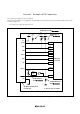
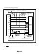
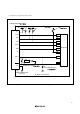
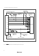
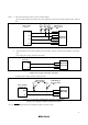
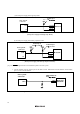
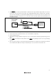
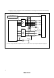
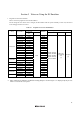

10. Figure 4.12 shows the interface circuit in the E8 emulator. Use this figure as a reference when determining
the pull-up resistance value.
RxD
SCLK
74LVC125A
Vcc
BUSY
RESET
Emulator control circuit
User system connector
9
13
8
74LVC125A
11
1
100kΩ
100kΩ
5
TxD
[*1]
3
CNVss
EPM
4
CE
7
10kΩ
100kΩ
22Ω
22Ω
22Ω
22Ω
22Ω
100kΩ
100kΩ
1MΩ
100kΩ
22Ω
22Ω
22Ω
3.3V
10kΩ
10kΩ
2SC2462
[*1] Power of the upper 74LVC125A is supplied from Vcc in the user system connector or power supply circuit (with power supply mode).
Power supply circuit
(Use only with power supply mode)
Figure 4.12 Interface Circuit in the E8 Emulator (Reference)
14