REJ10J1253-0300 E8 Emulator Additional Document for User's Manual R0E000080KCE00EP4 Renesas Microcomputer Development Environment System M16C Family / M16C/60 Series Notes on Connecting the M16C/62P, M16C/6N4, M16C/6N5, M16C/6NK, M16C/6NM, M16C/6NL and M16C/6NN Rev.3.
Keep safety first in your circuit designs! 1. Renesas Technology Corp. puts the maximum effort into making semiconductor products better and more reliable, but there is always the possibility that trouble may occur with them. Trouble with semiconductors may lead to personal injury, fire or property damage.
Contents Section 1 Specifications of the E8 Emulator ............................................................................................................1 Section 2 Connecting the Emulator with the User System ......................................................................................3 Section 3 Pin Assignments of the E8 Connector .....................................................................................................5 Section 4 Example of E8 Connection .....................
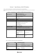
Section 1 Specifications of the E8 Emulator Table 1.1 shows the specifications of the M16C/62P and M16C/6N Groups E8 Emulator. This manual describes the M16C/6N4, M16C/6N5, M16C/6NK, M16C/6NM, M16C/6NL, M16C/6NN groups as the M16C/6N group. Table 1.1 Specifications of the M16C/62P and M16C/6N Groups E8 Emulator Target MCU M16C Family M16C/60 Series M16C/62P and M16C/6N Groups Usable operating mode Single-chip mode, Memory expansion mode * Microprocessor mode is not supported.
2
Section 2 Connecting the Emulator with the User System Before connecting an E8 emulator with the user system, a connector must be installed in the user system so that a user system interface cable can be connected. When designing the user system, refer to Figure 3.1, Pin Assignments of the E8 Connector, and Figure 4.1, Example of E8 Connection, shown in this manual. Before designing the user system, be sure to read the E8 emulator user’s manual and the hardware manual for related MCUs. Table 2.
4
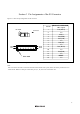
Section 3 Pin Assignments of the E8 Connector Figure 3.1 shows the pin assignments of the connector. Pin NO. Pin 1 mark Connector Pin2 Pin 14 Pin1 Pin 13 M16C/62P and M16C/6N MCU signals 1 2 P65( SCLK) Vss 3 CNVss 4 P55( EPM) 5 P67( TxD) 6 Vss 7 P50( CE) 8 Vcc 9 P64( BUSY) 10 Vss 11 P66( RxD) 12 Vss 13 Pin 1 mark 14 RESET Vss Figure 3.
6
Section 4 Example of E8 Connection The connecting examples are shown as follows. When using the emulator as a programmer, the specification of connection between the E8 and the MCUs is the same as shown in Figure 4.1. (1) In single-power supply and single-chip mode Pulled-up at 4.7kΩ or more Vcc Vcc Vcc Vcc Pulled-up at 4.7kΩ or more Vcc SCLK P65 RxD P66 TxD P67 BUSY P64 EPM P55 M16C/62P M16C/6N CE P50 CNVss CNVss Vcc * User logic RESET RESET Vss Pulled-up at 4.
(2) In single-power supply and memory expansion mode Pulled-up at 4.7kΩ to 22kΩ Pulled-up at 4.7Ω or more Vcc Vcc Vcc Vcc Vcc Pulled-up at 4.7Ω or more Vcc Vcc SCLK P65 RxD P66 TxD P67 BUSY P64 P55 [*1] EPM M16C/62P M16C/6N CE P50 CNVss CNVss Vcc User logic * RESET RESET Vss Pulled-up at 4.7Ω or more 14-pin 2.54mm pitch connector Pulled-down at 4.7Ω or more *: Open-collector buffer User System Figure 4.
(3) In dual-power supply and single-chip mode Pulled-up at 4.7kΩ or more Vcc1 Vcc1 Vcc1 Vcc1 Pulled-up at 4.7kΩ or more Vcc2 Pulled-up at 4.7kΩ or more Vcc SCLK P65 RxD P66 TxD P67 BUSY P64 EPM P55 CE P50 M16C/62P CNVss CNVss Vcc1 User logic * RESET RESET Vss Pulled-up at 4.7kΩ or more Pulled-down at 4.7kΩ or more 14-pin 2.54mm pitch connector *: Open-collector buffer User system Figure 4.
(4) In dual-power supply and memory expansion mode Pulled-up at 4.7kΩ to 22kΩ Pulled-up at 4.7Ω or more Vcc1 Vcc1 Vcc1 Vcc1 Pulled-up at 4.7Ω or more Vcc2 Vcc2 Pulled-up at 4.7Ω or more Vcc SCLK P65 RxD P66 TxD P67 BUSY P64 P55 [*1] EPM CE M16C/62P P50 CNVss CNVss Vcc1 User logic * RESET RESET Vss 14-pin 2.54mm pitch connector Pulled-up at 4.7Ω or more Pulled-down at 4.7Ω or more *: Open-collector buffer User System Figure 4.
Notes: 1. P64, P65, P66 and P67 pins are used by the E8 emulator. Connect the E8 emulator to the MCU pins. Pull up MCU pins and connect the E8 emulator to P65, P66 and P67. Vcc Vcc Vcc (Vcc1) (Vcc1) (Vcc1) User system connector P 65 1 P 65/ SCLK 5 P 67/TxD P67 P66 P64 Pulled- up at 4.7k Ω or more 11 P 66 /RxD 9 P 64 / BUSY M16C/62P M16C/6N Figure 4.5 Connection of E8 Emulator and MCU 2. The E8 emulator uses the P50 and P55 pins for the MCU control. Connect the E8 emulator to the MCU pins.
(3) In dual-power supply and single-chip mode Vcc2 User system connector Pulled-up at 4.7kΩ or more 4 P55/ EPM EPM M16C/62P P50/ CE CE Figure 4.8 Connection of E8 Emulator and P50 and P55 Pins (Dual-power Supply and Single-chip Mode) (4) In dual-power supply and memory expansion mode Vcc2 Pulled-up at 4.7kΩ to 22kΩ Vcc2 Pulled-up at 4.7Ω or more User system connector 4 P55/EPM EPM M16C/62P P50/CE CE Figure 4.
4. The RESET pin is used by the E8 emulator. Therefore use an open-collector output buffer or a CR reset circuit as the reset circuit of the user system. The recommended pull-up value is 4.7kΩ or more. The MCU can be reset by outputting “L” from the E8 emulator. However, if a reset circuit on the user system is the H-output type reset IC, it cannot be set “L” in the reset circuit on the user system and the E8 emulator will not operate normally.
10. Figure 4.12 shows the interface circuit in the E8 emulator. Use this figure as a reference when determining the pull-up resistance value. User system connector Power supply circuit (Use only with power supply mode) 10kΩ [*1] 100kΩ 74LVC125A Emulator control circuit 100kΩ Vcc 8 22Ω SCLK 22Ω CNVss 3 22Ω EPM 4 22Ω CE 7 22Ω RxD 11 1 100kΩ 1MΩ 100kΩ 74LVC125A 100kΩ 100kΩ 22Ω TxD 22Ω BUSY 22Ω RESET 5 9 13 3.
Section 5 Notes on Using the E8 Emulator 1. Program area for the E8 emulator Table 5.1 lists the program area for the E8 emulator. Do not change this area. If this area is changed, the E8 emulator will not operate normally. In this case, disconnect to the debugger and then reconnect. Table 5.
Figure 5.1 [Firmware Location] Tab of the [Emulator Setting] Dialog Box 2. When the emulator system is initiated, it initializes the general registers and part of the control registers as shown in Table 5.2. Table 5.
5. SFR used by the program for the E8 emulator As the SFR listed in Table 5.3 is used by the program for the E8 emulator, do not change a value. Otherwise, the E8 emulator cannot be controlled. Note that UART1 transmit interrupt control register S1TIC and UART1 receive interrupt control register S1RIC always read out the value of using the emulator. Also, they are not initialized by selecting [Debug] -> [Reset CPU] or with the RESET command.
7. Debugging of the watchdog timer When debugging the user program using the watchdog timer, select the [Debugging of program that uses WDT.] check box in the [Firmware Location] tab of the [Emulator Setting] dialog box. By selecting this box, the watchdog timer is refreshed during the operation of the program for the E8 emulator. If a memory is accessed by the memory reference or modification, the watchdog timer will be refreshed by the program for the E8 emulator.
Figure 5.3 [ID Code verification] Dialog Box [Note on Program Flash mode] When the ID code is specified by the -ID option of the lmc30, download the MOT file or HEX file. When the X30 file is downloaded, the ID code is not effective. When downloading the X30 file, specify the ID code using an assembler directive command such as “.BYTE”. The file to which the ID code specified by the assembler directive command “.ID” is output varies depending on the version of the assembler.
15. Reserved area The addresses not specified in the Hardware Manual for the M16C/62P and M16C/6N Groups are reserved area. Do not change the contents. Otherwise, the E8 emulator cannot be controlled. 16. Debugging in the stop mode or wait mode When debugging in the stop or wait mode, the program cannot be stopped by the E8 emulator. If you attempt to stop the program during the stop or wait mode, the emulator will be uncontrollable.
19. “Go to cursor” function The "Go to cursor" function is realized by using an address match break. Therefore, when you execute the Go to cursor" command, all the address match breaks you set become invalid, while all the PC breaks remain valid. 20. Note on PC break point When downloading a user program after changing it, the address setting of a PC break may not be corrected normally depending on the changes.
24. Notes on the E8 emulator power supply When writing reliability required program with the E8 emulator under the mass production, do not use the E8 emulator power supply function. Separately supply appropriate voltage according to the MCU programming to the user system. Since the supplied voltage from the E8 emulator depends on the quality of the USB power supply of the PC, its precision is not guaranteed.
Section 6 Setup the Debugger 1. Emulator Setting dialog box [Emulator Setting] dialog box is provided for setting the items that need to be set when the debugger starts up. The contents set from this dialog box other than “Power supply” are also effective the next time the debugger starts. When starting up the debugger first time after creating the new project work space, [Emulator Setting] dialog box is displayed with the Wizard. Figure 6.1 [Emulator Setting] Dialog Box.
2. Emulator mode Tab The selection of the device, the specification of the mode, and the setting of the power supply are done in the [Emulator mode] tab of the [Emulator Setting] dialog box. Figure 6.2 [Emulator mode] Tab [Device] Select the name of the MCUs to be used from the [Device] drop-down list box. [Mode] - Erase Flash and Connect When starting up the debugger, erase the flash memory data of the MCUs. The program for the E8 emulator is written at the same time.
4 MCU Setting Tab In the [MCU Setting] tab, set the operating condition of MCU used in the user system. Figure 6.3 [MCU Setting] Dialog Box Specify the processor mode Specify the processor mode according to the user system. One of the followings can be specified. - Single-Chip Mode - Memory Expansion Mode Memory Expansion Mode When the memory expansion mode is selected, specify whether you use the memory space expansion function or not.
Section 7 Command for Memory Space Expansion Function 4MB Mode 1. Command for Memory Space Expansion Function 4MB Mode The followings show the command for memory space expansion function 4MB mode. These commands can be executed in the command line window. Command Memory_Compare_Ext Memory_Display_Ext Memory_Fill_Ext Memory_Find_Ext Memory_Move_Ext Description Compares the memory area (between the start address and the end address) with the memory starting at destination address. Displays memory contents.
Memory_Display_Ext Abbreviation: MDE Description: Displays memory contents. This cannot be used during the program execution.
Memory_Find_Ext Abbreviation: MIE Description: Finds a string in a memory range. This cannot be used during the program execution.
Section 8 Applicable Tool Chain and Partner Tools With the M16C/62P and M16C/6N Groups E8 emulator, you can debug a module created by the inhouse tool chain and third-party products listed in Table 8.1 below. Table 8.1 Applicable Tool Chain and Partner Tools Tool chain Partner tools M3T-NC30WA V.5.20 Release 01 or later TASKING M16C C/C++/EC++ Compiler V.2.3r1 or later IAR EWM16C V.2.
*.cpp main() { class DerivedClass ClassObj; ClassObj.DerivedFunc(); return; } void BaseClass::BaseFunc(void) { m_iBase = 0x1234; } void DerivedClass::DerivedFunc(void) { BaseFunc(); m_iDerive = 0x1234; } ///////////////////////////////////////////////////////// ///////////////////////////////////////////////////////// Case 1: If the PC value resides in the main() function : Cannot be referenced (*1) (2)"ClassObj.__b_BaseClass.
E8 Emulator Additional Document for User's Manual Notes on Connecting the M16C/62P, M16C/6N4, M16C/6N5, M16C/6NK, M16C/6NM, M16C/6NL and M16C/6NN Publication Date: December 16, 2005 November 01, 2006 Rev.1.00 Rev.3.00 Published by: Sales Strategic Planning Div. Renesas Technology Corp. Edited by: Microcomputer Tool Development Department Renesas Solutions Corp. © 2006. Renesas Technology Corp. and Renesas Solutions Corp., All rights reserved. Printed in Japan.
E8 Emulator Additional Document for User's Manual