
User`s manual

E8a Emulator Section 5 Examples of E8a Connections
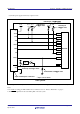
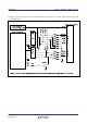
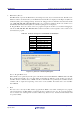
9. Figure 5.12 shows the interface circuit in the E8a emulator. Use this figure as a reference when determining the pull-
up resistance value.
Figure 5.12 Interface Circuit Inside the E8a Emulator (For Reference)
REJ10J1640-0400
Rev.4.00 Page 12 of 31
100kΩ
1MΩ
100kΩ
10kΩ
100kΩ
1kΩ
10kΩ
Apr 30, 2010