User’s Manual E8a Emulator Additional Document for User's Manual R0E00008AKCE00EP4 Renesas Microcomputer Development Environment System M16C Family / M16C/60 Series Notes on Connecting the M16C/62P, M16C/6N4, M16C/6N5, M16C/6NK, M16C/6NM, M16C/6NL and M16C/6NN All information contained in these materials, including products and product specifications, represents information on the product at the time of publication and is subject to change by Renesas Electronics Corporation without notice.
Notice 1. 2. 3. 4. 5. 6. 7. All information included in this document is current as of the date this document is issued. Such information, however, is subject to change without any prior notice. Before purchasing or using any Renesas Electronics products listed herein, please confirm the latest product information with a Renesas Electronics sales office.
Contents Section 1 Inside the E8a Emulator User’s Manual...................................................................................................1 Section 2 E8a Emulator Specifications ....................................................................................................................2 Section 3 Connecting the E8a Emulator to the User System ..................................................................................3 Section 4 E8a Connecting Connector Pin Assignments.......
E8a Emulator Section 1 Inside the E8a Emulator User’s Manual Section 1 Inside the E8a Emulator User’s Manual The E8a emulator manual consists of two documents: the E8a User’s Manual and the E8a Additional Document for User’s Manual (this document). Be sure to read BOTH documents before using the E8a emulator. (1) E8a Emulator User’s Manual The E8a Emulator User’s Manual describes the hardware specifications and how to use the emulator debugger.
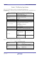
E8a Emulator Section 2 E8a Emulator Specifications Section 2 E8a Emulator Specifications Table 2.1 shows the E8a emulator specifications for the M16C/62P and M16C/6N Groups. This manual describes the M16C/6N4, M16C/6N5, M16C/6NK, M16C/6NM, M16C/6NL and M16C/6NN Groups as the M16C/6N Group. Table 2.
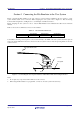
E8a Emulator Section 3 Connecting the E8a Emulator to the User System Section 3 Connecting the E8a Emulator to the User System Before connecting the E8a emulator to the user system, a connector must be installed in the user system so a user system interface cable can be connected. When designing the user system, refer to Figure 4.1 “E8a Connecting Connector Pin Assignments”, and Figures 5.1 to 5.4 “Example of an E8a Connection”.
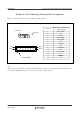
E8a Emulator Section 4 E8a Connecting Connector Pin Assignments Section 4 E8a Connecting Connector Pin Assignments Figure 4.1 shows the pin assignments for the E8a connecting connector. Pin No. Pin 1 mark Connector Pin 2 Pin 14 Pin 1 Pin 13 Pin 1 mark M16C/62P and M16C/6N MCU signals 1 2 P65 (SCLK) Vss 3 4 CNVss P55 (EPM) 5 P67 (TxD) 6 7 Vss P50 (CE) 8 Vcc 9 P64 (BUSY) 10 11 Vss P66 (RxD) 12 Vss 13 RESE T Vss 14 Figure 4.
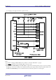
E8a Emulator Section 5 Examples of E8a Connections Section 5 Examples of E8a Connections The following show connection examples. When using the emulator as a programmer, the connection specification between the E8a and the MCUs is the same as shown below. (1) In single power supply and single-chip mode Figure 5.1 Example of an E8a Connection (Single Power Supply and Single-chip Mode) Note: 1. For details on setting pins P50, P55, P64 and P65, refer to numbers 1 and 2 of “Points to Remember” on page 9.
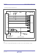
E8a Emulator Section 5 Examples of E8a Connections (2) In single power supply and memory expansion mode Figure 5.2 Example of an E8a Connection (Single Power Supply and Memory Expansion Mode) Notes: 1. For details on setting pins P64 and P65 refer to number 1 of “Points to Remember” on page 9. 2. The HOLD signal cannot be used. Pull up P55 on the user system. 3. P50 is used as the WRL#/WR# pin. The E8a emulator outputs “H” to the CE pin when going to boot mode (resetting the MCU).
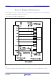
E8a Emulator Section 5 Examples of E8a Connections (3) In dual power supply and single-chip mode Vcc1 Vcc1 Vcc1 Pulled up at 4.7k Pulled up at 4.7k Vcc2 Vcc SCLK P65 [*1] RxD P66 TxD P67 BUSY P64 [*1] EPM P55 [*1] CE M16C/62P P50 CNVss CNVss Vcc1 User logic * RESET RESET Vss Pulled up at 4.7k Pulled down at 4.7k 14-pin 2.54mm pitch connector * : Open-collector buffer User system Figure 5.3 Example of an E8a Connection (Dual Power Supply and Single-chip Mode) Note: 1.
E8a Emulator Section 5 Examples of E8a Connections (4) In dual power supply and memory expansion mode Pulled up at 4.7k Pulled up at 4.7k or more Vcc1 Vcc1 Vcc1 Vcc2 k Vcc2 Pulled up at 4.7k or more Vcc SCLK P65 [*1] RxD P66 TxD P67 BUSY P64 [*1] EPM P55 [*2] CE M16C/62P P50 CNVss CNVss Vcc 1 User logic * RESET RESET Vss Pulled up at 4.7k or more Pulled down at 4.7k 14-pin 2.54mm pitch connector or more * : Open-collector buffer User system Figure 5.
E8a Emulator Section 5 Examples of E8a Connections Points to Remember 1. Pins P64, P65, P66 and P67 are used exclusively by the E8a emulator. Connect the E8a emulator to the MCU pins. Connect pins P66 and P67 to the E8a emulator after pulling up the MCU pins at the Vcc (Vcc1) level. For P64 and P65, pull up the pins at the Vcc (Vcc1) level or pull down them according to the MCU pin state after disconnecting the E8a emulator. P64 may be in a Hiz state while the E8a emulator is active.
E8a Emulator Section 5 Examples of E8a Connections (2) Single power supply and memory expansion mode Figure 5.7 Connection of E8a Emulator and Pins P50 and P55 (Single Power Supply and Memory Expansion Mode) Note: 1. The HOLD signal cannot be used. Pull up P55 at the Vcc level on the user system. (3) In dual power supply and single-chip mode Pull up P55 at the Vcc2 level or pull down it according to the MCU pin state after disconnecting the E8a emulator.
E8a Emulator Section 5 Examples of E8a Connections 3. The E8a emulator uses the CNVss pin for MCU control. Pull down the E8a emulator and MCU pins and connect the E8a emulator. Figure 5.10 E8a Emulator and CNVss Pin Connection 4. The RESET pin is used by the E8a emulator. Therefore, use an open-collector output buffer or a CR reset circuit as the reset circuit for the user system. The recommended pull-up value is 4.7 kΩ or more. The MCU can be reset by outputting “L” from the E8a emulator.
E8a Emulator Section 5 Examples of E8a Connections 1MΩ 100kΩ 100kΩ 10kΩ 10kΩ 1kΩ 100kΩ 9. Figure 5.12 shows the interface circuit in the E8a emulator. Use this figure as a reference when determining the pullup resistance value. Figure 5.12 Interface Circuit Inside the E8a Emulator (For Reference) REJ10J1640-0400 Rev.4.
E8a Emulator Section 6 Notes on Using the E8a Emulator Section 6 Notes on Using the E8a Emulator 1. Program area for the E8a emulator Table 6.1 lists the program areas allotted for the E8a emulator. Do not change this area allocation, otherwise the E8a emulator will not control the MCU. If settings were changed, disconnect the debugger and then reconnect it. Table 6.1 Program Area for the E8a Emulator ROM Size Group Part No.
E8a Emulator Section 6 Notes on Using the E8a Emulator Figure 6.1 [Firmware Location] Tab of the [Emulator Setting] Dialog Box 2. When the system is launched, the E8a emulator initializes the general registers and some of the flag registers as shown in Table 6.2. Table 6.
E8a Emulator 5. Section 6 Notes on Using the E8a Emulator SFRs used by the E8a emulator program As the SFRs listed in Table 6.3 are used by the E8a emulator program, do not change any of these values. If these values are changed, the E8a emulator cannot control the MCU. Note that UART1 transmit interrupt control register S1TIC and UART1 receive interrupt control register S1RIC always read out values used by the emulator.
E8a Emulator 7. Section 6 Notes on Using the E8a Emulator Debugging using the watchdog timer When debugging the user program using the watchdog timer, click the [Debugging of program that uses WDT.] check box in the [Firmware Location] tab of the [Emulator Setting] dialog box. By clicking this box, the E8a emulator program refreshes the watchdog timer during program operation.
E8a Emulator 8. Section 6 Notes on Using the E8a Emulator Flash memory ID code This MCU function prevents the Flash memory from being read out by anyone other than the user. The ID code in Table 6.4 written to the flash memory of the MCU must match the ID code displayed in the Figure 6.3 [ID Code verification] dialog box at debugger startup, otherwise the debugger cannot be launched. Note that when the ID code is FFh, FFh, FFh, FFh, FFh, FFh, FFh, the ID code is regarded as undefined.
E8a Emulator Section 6 Notes on Using the E8a Emulator 10. Memory access during emulation execution When referring to or modifying the memory contents, the user program is temporarily halted. For this reason, a real-time emulation cannot be performed. When a real-time emulation is necessary during a program execution, disable the automatic update in the watch window or fix the display in the memory window before running the program so that memory accesses do not occur during an execution. 11.
E8a Emulator Section 6 Notes on Using the E8a Emulator 18. Exceptional step execution a) Software interrupt instruction Step execution cannot be performed in the internal processing of instructions (undefined, overflow, BRK and INT) which generate a software interrupt continuously in the program. Example: INT instruction NOP NOP INT #3 NOP JMP MAIN INT_3: NOP NOP NOP REIT Passes through if the STEP execution is carried out. Program should be stopped at this address.
E8a Emulator Section 6 Notes on Using the E8a Emulator 21. Note on debugging in CPU rewrite mode When debugging in CPU rewrite mode, do not rewrite in CPU block 0 area (addresses FF000h - FFFFFh) and block containing the E8a emulator program. If these areas are rewritten, the E8a emulator will not control the MCU. Do not halt the user program while setting up the CPU rewrite mode and releasing it. If halted, the E8a emulator may not control the MCU.
E8a Emulator Section 6 Notes on Using the E8a Emulator 26. DMAC during a user program halt When the user program is halted or when the memory is referred to or modified during user program execution, DMA transfer is disabled. In such cases, the E8a emulator sets the registers below as following. Therefore, if you refer to the registers below in the memory window, etc., it shows that DMA is disabled.
E8a Emulator Section 7 Debugger Setting Section 7 Debugger Setting 1. [Emulator Setting] dialog box The [Emulator Setting] dialog box is provided for setting items that need to be set when the debugger is launched. The contents set from this dialog box (excluding [Power Supply] group box items) also become valid the next time the debugger is launched. When launching the debugger for the first time after creating a new project work space, the [Emulator Setting] dialog box is displayed with the Wizard.
E8a Emulator Section 7 Debugger Setting 2. [Emulator mode] tab Device selection, mode specification and power supply setting are made from the [Emulator mode] tab of the [Emulator Setting] dialog box. Figure 7.2 [Emulator mode] Tab [MCU Group] Select the name of the MCU group to be used from the [MCU Group] drop-down list. [Device] Select the type of MCU to be used from the [Device] drop-down list. REJ10J1640-0400 Rev.4.
E8a Emulator Section 7 Debugger Setting [Mode] - Erase Flash and Connect When starting the debugger, the E8a emulator erases the Flash memory data for the MCUs and simultaneously writes the E8a emulator program. - Keep Flash and Connect When launching the debugger, the E8a emulator retains the Flash memory data for the MCUs. Note that the area for the E8a emulator program and the vector area used by the E8a emulator will change. - Program Flash The E8a emulator starts as a simple programmer.
E8a Emulator Section 7 Debugger Setting 4. [MCU Setting] Tab In the [MCU Setting] tab, set the operating condition of the MCU used in the user system. Figure 7.3 [MCU Setting] Tab Specify processor mode Specify the processor mode according to the user system. One of the following can be specified: - Single-Chip Mode - Memory Expansion Mode Memory Expansion Mode When Memory Expansion Mode is selected, specify whether the memory space expansion function will be used.
E8a Emulator Section 7 Debugger Setting 5. [Communication Baud Rate] Tab Select communication baud rate between the E8a and MCU in the [Communication Baud Rate] tab. 2000000bps (default setting) should be selected. Figure 7.4 [Communication Baud Rate] Tab REJ10J1640-0400 Rev.4.
E8a Emulator Section 8 Command for Memory Space Expansion Function 4 MB Mode Section 8 Command for Memory Space Expansion Function 4 MB Mode 1. Command for Memory Space Expansion Function 4 MB Mode The following show the command for memory space expansion function 4 MB mode. These commands can be executed in the command line window.
E8a Emulator Section 8 Command for Memory Space Expansion Function 4 MB Mode Memory_Display_Ext Abbreviation: MDE Description: Displays memory contents. This cannot be used during program execution.
E8a Emulator Section 8 Command for Memory Space Expansion Function 4 MB Mode Memory_Find_Ext Abbreviation: MIE Description: Finds a string in a memory range. This cannot be used during program execution.
E8a Emulator Section 9 Applicable Tool Chain and Third-party Products Section 9 Applicable Tool Chain and Third-party Products With the M16C/62P and M16C/6N Group E8a emulator, you can debug modules created by the inhouse tool chain and third-party tools listed in Table 9.1 below. Table 9.1 Applicable Tool Chain and Third-party Tools Tool chain Third-party tools M3T-NC30WA V.5.20 Release 01 or later TASKING M16C C/C++/EC++ Compiler V.2.3r1 or later IAR EWM16C V.2.
E8a Emulator Section 9 Applicable Tool Chain and Third-party Products *.cpp main() { class DerivedClass ClassObj; ClassObj.DerivedFunc(); return; } void BaseClass::BaseFunc(void) { m_iBase = 0x1234; } void DerivedClass::DerivedFunc(void) { BaseFunc(); m_iDerive = 0x1234; } ///////////////////////////////////////////////////////// < Watch window registration example> ///////////////////////////////////////////////////////// Case 1: If the PC value resides in the main() function (1)"ClassObj.
E8a Emulator (R0E00008AKCE00) Notes on Connecting the M16C/62P, M16C/6N4, M16C/6N5, M16C/6NK, M16C/6NM, M16C/6NL and M16C/6NN Publication Date: Apr 30, 2010 Rev.4.
http://www.renesas.com SALES OFFICES Refer to "http://www.renesas.com/" for the latest and detailed information. Renesas Electronics America Inc. 2880 Scott Boulevard Santa Clara, CA 95050-2554, U.S.A. Tel: +1-408-588-6000, Fax: +1-408-588-6130 Renesas Electronics Canada Limited 1101 Nicholson Road, Newmarket, Ontario L3Y 9C3, Canada Tel: +1-905-898-5441, Fax: +1-905-898-3220 Renesas Electronics Europe Limited Dukes Meadow, Millboard Road, Bourne End, Buckinghamshire, SL8 5FH, U.
E8a Emulator (R0E00008AKCE00) Additional Document for User's Manual REJ10J1640-0400