
Data Sheet

ICL7106, ICL7107, ICL7107S
FN3082 Rev 9.00 Page 9 of 17
October 24, 2014
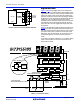
System Timing
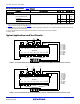
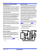
Figure 9 shows the clocking arrangement used in the ICL7106
and ICL7107. Two basic clocking arrangements can be used:
1. Figure 9A
. An external oscillator connected to pin 40.
2. Figure 9B
. An R-C oscillator using all three pins.
The oscillator frequency is divided by four before it clocks the
decade counters. It is then further divided to form the three
convert-cycle phases. These are signal integrate (1000 counts),
reference deintegrate (0 to 2000 counts) and auto-zero (1000 to
3000 counts). For signals less than full scale, auto-zero gets the
unused portion of reference de-integrate. This makes a complete
measure cycle of 4,000 counts (16,000 clock pulses)
independent of input voltage. For three readings/second, an
oscillator frequency of 48kHz would be used.
To achieve maximum rejection of 60Hz pickup, the signal
integrate cycle should be a multiple of 60Hz. Oscillator
frequencies of 240kHz, 120kHz, 80kHz, 60kHz, 48kHz, 40kHz,
33
1
/
3
kHz, etc., should be selected. For 50Hz rejection, oscillator
frequencies of 200kHz, 100kHz, 66
2
/
3
kHz, 50kHz, 40kHz, etc.,
would be suitable. Note that 40kHz (2.5 readings/second) will
reject both 50Hz and 60Hz (also 400Hz and 440Hz).
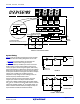
7
SEGMENT
DECODE
TO
SEGMENT
0.5mA
8mA
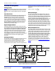
DIGITAL GROUND
TYPICAL SEGMENT OUTPUT
V+
LATCH
7
SEGMENT
DECODE
LOGIC CONTROL
7
SEGMENT
DECODE
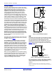
1000’s 100’s 10’s 1’s
TO SWITCH DRIVERS
FROM COMPARATOR OUTPUT
DIGITAL
GROUND
4
CLOCK
40 39 38
OSC 1
OSC 2
OSC 3
V+
TEST
500Ω
COUNTER
COUNTER COUNTER COUNTER
1
V+
37
27
c
a
b
c
d
f
g
e
a
b
a
b
c
d
f
g
e
a
b
c
d
f
g
e
†
†
THREE INVERTERS
ONE INVERTER SHOWN FOR CLARITY
FIGURE 8. ICL7107 DIGITAL SECTION
CLOCK
INTERNAL TO PART
40 39
38
GND ICL7107
4
CLOCK
INTERNAL TO PART
40 39
38
4
RC OSCILLATOR
R
C
TEST ICL7106
FIGURE 9B.
FIGURE 9. CLOCK CIRCUITS
FIGURE 9A.