
Data Sheet

FN3082 Rev 9.00 Page 17 of 17
October 24, 2014
ICL7106, ICL7107, ICL7107S
Intersil products are manufactured, assembled and tested utilizing ISO9001 quality systems as noted
in the quality certifications found at www.intersil.com/en/support/qualandreliability.html
Intersil products are sold by description only. Intersil may modify the circuit design and/or specifications of products at any time without notice, provided that such
modification does not, in Intersil's sole judgment, affect the form, fit or function of the product. Accordingly, the reader is cautioned to verify that datasheets are
current before placing orders. Information furnished by Intersil is believed to be accurate and reliable. However, no responsibility is assumed by Intersil or its
subsidiaries for its use; nor for any infringements of patents or other rights of third parties which may result from its use. No license is granted by implication or
otherwise under any patent or patent rights of Intersil or its subsidiaries.
For information regarding Intersil Corporation and its products, see www.intersil.com
For additional products, see www.intersil.com/en/products.html
© Copyright Intersil Americas LLC 2002-2014. All Rights Reserved.
All trademarks and registered trademarks are the property of their respective owners.
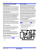
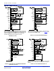
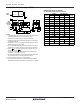
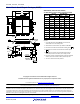
Metric Plastic Quad Flatpack Packages (MQFP)
D
D1
E
E1
-A-
PIN 1
A2
A1
A
12
o
-16
o
12
o
-16
o
0
o
-7
o
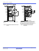
0.40
0.016
MIN
L
0
o
MIN
PLANE
b
0.005/0.009
0.13/0.23
WITH PLATING
BASE METAL
SEATING
0.005/0.007
0.13/0.17
b1
-B-
e
0.008
0.20
A-B SD SCM
0.076
0.003
-C-
-D-
-H-
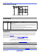
Q44.10x10 (JEDEC MS-022AB ISSUE B)
44 LEAD METRIC PLASTIC QUAD FLATPACK PACKAGE
SYMBOL
INCHES MILLIMETERS
NOTESMIN MAX MIN MAX
A - 0.096 - 2.45 -
A1 0.004 0.010 0.10 0.25 -
A2 0.077 0.083 1.95 2.10 -
b 0.012 0.018 0.30 0.45 6
b1 0.012 0.016 0.30 0.40 -
D 0.515 0.524 13.08 13.32 3
D1 0.389 0.399 9.88 10.12 4, 5
E 0.516 0.523 13.10 13.30 3
E1 0.390 0.398 9.90 10.10 4, 5
L 0.029 0.040 0.73 1.03 -
N44 447
e 0.032 BSC 0.80 BSC -
Rev. 2 4/99
NOTES:
1. Controlling dimension: MILLIMETER. Converted inch
dimensions are not necessarily exact.
2. All dimensions and tolerances per ANSI Y14.5M-1982.
3. Dimensions D and E to be determined at seating plane .
4. Dimensions D1 and E1 to be determined at datum plane
.
5. Dimensions D1 and E1 do not include mold protrusion.
Allowable protrusion is 0.25mm (0.010 inch) per side.
6. Dimension b does not include dambar protrusion. Allowable
dambar protrusion shall be 0.08mm (0.003 inch) total.
7. “N” is the number of terminal positions.
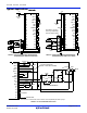
-C-
-H-