
Data Sheet

ICL7106, ICL7107, ICL7107S
FN3082 Rev 9.00 Page 11 of 17
October 24, 2014
Typical Applications
The ICL7106 and ICL7107 may be used in a wide variety of
configurations. The circuits which follow show some of the
possibilities, and serve to illustrate the exceptional versatility of
these A/D converters.
The following application notes contain very useful information
on understanding and applying this part and are available from
Intersil Corporation.
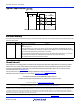
Application Notes
NOTE # DESCRIPTION
AN016 “Selecting A/D Converters”
AN017 “The Integrating A/D Converter”
AN018 “Do’s and Don’ts of Applying A/D Converters”
AN023 “Low Cost Digital Panel Meter Designs”
AN046 “Building a Battery-Operated Auto Ranging DVM with the ICL7106”
AN052 “Tips for Using Single Chip 3
1
/
2
Digit A/D Converters”
AN9609 “Overcoming Common Mode Range Issues When Using Intersil
Integrating Converters”
Typical Applications
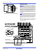
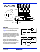
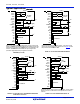
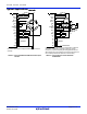
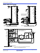
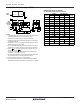
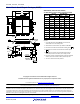
FIGURE 11. ICL7106 USING THE INTERNAL REFERENCE FIGURE 12. ICL7107 USING THE INTERNAL REFERENCE
28
40
39
38
37
36
35
34
33
32
31
30
29
27
26
25
24
23
22
21
OSC 1
OSC 2
OSC 3
TEST
REF HI
REF LO
C
REF
C
REF
COMMON
IN HI
IN LO
A-Z
BUFF
INT
V -
G2
C3
A3
G3
BP
100pF
TO PIN 1
SET V
REF
= 100mV
0.1µF
0.01µF
1MΩ
100kΩ
1kΩ 22kΩ
IN
+
-
9V
47kΩ
0.22µF
0.47µF
TO BACKPLANE
TO DISPLAY
Values shown are for 200mV full scale, 3 readings/sec., floating supply
voltage (9V battery).
+
-
Values shown are for 200mV full scale, 3 readings/sec. IN LO may be
tied to either COMMON for inputs floating with respect to supplies, or
GND for single ended inputs. (See discussion in “
Analog COMMON” on
page 7.)
28
40
39
38
37
36
35
34
33
32
31
30
29
27
26
25
24
23
22
21
OSC 1
OSC 2
OSC 3
TEST
REF HI
REF LO
C
REF
C
REF
COMMON
IN HI
IN LO
A-Z
BUFF
INT
V -
G2
C3
A3
G3
GND
100pF
TO PIN 1
SET V
REF
= 100mV
0.1µF
0.01µF
1MΩ
100kΩ
1kΩ 22kΩ
IN
+
-
47kΩ
0.22µF
0.47µF
TO DISPLAY
+5V
-5V