
User System Interface Board User's Manual
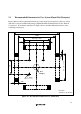
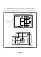
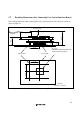
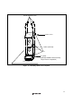
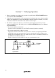
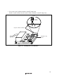
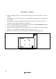
Table Of Contents
- Cover
- Cautions
- IMPORTANT INFORMATION
- SAFETY PAGE
- Preface
- Contents
- Section 1 Configuration
- Section 2 Environmental Conditions
- Section 3 Product Specifications
- Section 4 User Interface Specifications
- Section 5 Connection Procedures
- 5.1 Connecting User System Interface Board to User System
- 5.2 Connecting User System Interface Board to EV-Chip Board
- 5.3 Recommended Dimensions for User System Mount Pad (Footprint)
- 5.4 Dimensions for EV-Chip Board and User System Interface Board
- 5.5 Resulting Dimensions after Connecting User System Interface Board
- Section 6 Installing the MCU to the User System
- Section 7 Verifying Operation
- Section 8 Notice
- Colophon
20
Section 8 Notice
1.
Before connecting any parts or cables, make sure that pin 1 on the both sides are correctly
aligned.
2.
Do not apply excessive force to the user system interface board while it is connected to the
user system.
3.
The dimensions of the recommended mount pad for the IC socket for this user system
interface board are different from those of the MCU.
4.
This user system interface board is specifically designed for the HS7046EPH60H emulator.
Do not use this board with any other emulator.
5.
When power is not supplied to the Vcc pin on the user system interface board, the emulator
displays ** VCC DOWN. The emulator will not operate correctly.
6. The P1 short connector is used for testing. Do not remove the inserted jumper pin.
P1
13
Figure 16 P1 Jumper Socket