
User System Interface Board User's Manual
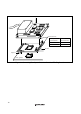
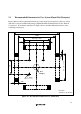
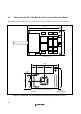
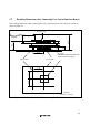
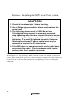
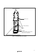
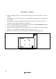
Table Of Contents
- Cover
- Cautions
- IMPORTANT INFORMATION
- SAFETY PAGE
- Preface
- Contents
- Section 1 Configuration
- Section 2 Environmental Conditions
- Section 3 Product Specifications
- Section 4 User Interface Specifications
- Section 5 Connection Procedures
- 5.1 Connecting User System Interface Board to User System
- 5.2 Connecting User System Interface Board to EV-Chip Board
- 5.3 Recommended Dimensions for User System Mount Pad (Footprint)
- 5.4 Dimensions for EV-Chip Board and User System Interface Board
- 5.5 Resulting Dimensions after Connecting User System Interface Board
- Section 6 Installing the MCU to the User System
- Section 7 Verifying Operation
- Section 8 Notice
- Colophon

16
Section 6 Installing the MCU to the User System
CAUTION
1. Check the location of pin 1 before inserting.
2. Use a Philips-type screwdriver whose head matches the
screw head.
3. The tightening torque must be 0.054 N•m or less.
If the applied torque cannot be accurately measured,
stop tightening when the force required to turn the screw
becomes significantly greater than that needed when first
tightening. If a screw is tightened too much, the screw
head may break or an IC socket contact error may be
caused by a crack in the IC socket solder.
4. If the MCU does not operate correctly, cracks might have
occurred in the solder. Check conduction with a tester
and re-solder the IC socket if necessary.
Check the location of pin 1 before inserting the MCU into the IC socket on the user system, as
shown in figure 13. After inserting the MCU, fasten the socket cover with the provided four
screws (M2.0
x
6 mm). Take special care, such as manually securing the IC socket soldered area,
to prevent the IC socket from being damaged by overtightening the screws or twisting the
components.