
User System Interface Board User's Manual
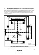
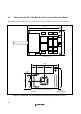
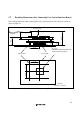
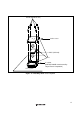
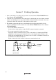
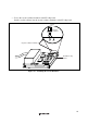
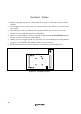
Table Of Contents
- Cover
- Cautions
- IMPORTANT INFORMATION
- SAFETY PAGE
- Preface
- Contents
- Section 1 Configuration
- Section 2 Environmental Conditions
- Section 3 Product Specifications
- Section 4 User Interface Specifications
- Section 5 Connection Procedures
- 5.1 Connecting User System Interface Board to User System
- 5.2 Connecting User System Interface Board to EV-Chip Board
- 5.3 Recommended Dimensions for User System Mount Pad (Footprint)
- 5.4 Dimensions for EV-Chip Board and User System Interface Board
- 5.5 Resulting Dimensions after Connecting User System Interface Board
- Section 6 Installing the MCU to the User System
- Section 7 Verifying Operation
- Section 8 Notice
- Colophon
15
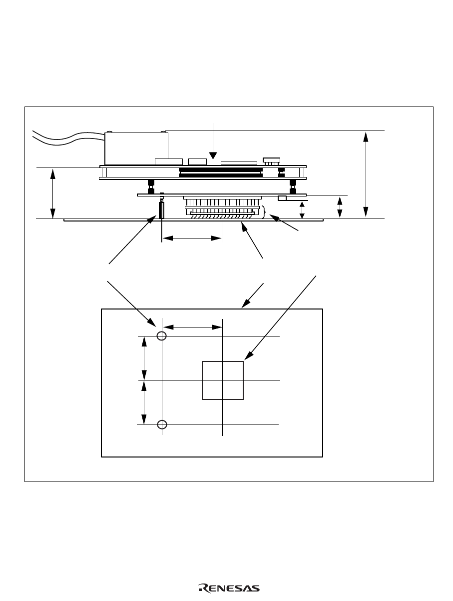
5.5 Resulting Dimensions after Connecting User System Interface Board
The resulting dimensions, after connecting the user system interface board to the user system, are
shown in figure 12.
EV-chip board
11.5
Unit: mm
Tolerance: ±1.0 mm
User system
31.0
29.5
29.5
31.0
Spacer (φ6.0)
35.2
IC socket
(NQPACK144SD manufactured by
Tokyo Eletech Corporation)
13.2
60.2
Figure 12 Resulting Dimensions after Connecting User System Interface Board