
User System Interface Board User's Manual
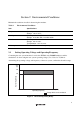
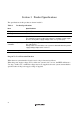
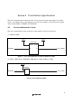
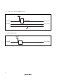

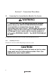
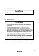
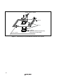
Table Of Contents
- Cover
- Cautions
- IMPORTANT INFORMATION
- SAFETY PAGE
- Preface
- Contents
- Section 1 Configuration
- Section 2 Environmental Conditions
- Section 3 Product Specifications
- Section 4 User Interface Specifications
- Section 5 Connection Procedures
- 5.1 Connecting User System Interface Board to User System
- 5.2 Connecting User System Interface Board to EV-Chip Board
- 5.3 Recommended Dimensions for User System Mount Pad (Footprint)
- 5.4 Dimensions for EV-Chip Board and User System Interface Board
- 5.5 Resulting Dimensions after Connecting User System Interface Board
- Section 6 Installing the MCU to the User System
- Section 7 Verifying Operation
- Section 8 Notice
- Colophon
8
Section 5 Connection Procedures
5.1 Connecting User System Interface Board to User System
WARNING
Always switch OFF the user system and the emulator
product before the USER SYSTEM INTERFACE BOARD
is connected to or removed from any part. Before
connecting, make sure that pin 1 on both sides are correctly
aligned. Failure to do so will result in a FIRE HAZARD and
will damage the user system and the emulator product or
will result in PERSONAL INJURY. The USER PROGRAM will
be LOST.
To connect the cable head to the user system, follow the instructions below.
5.1.1 Installing IC Socket
Solder the IC socket for an FP-144F package to the user system.
CAUTION
Be sure to completely solder the leads so that the solder
slops gently over the leads and forms solder fillets. (Use
slightly more solder than the MCU.)