. Powerful Processors – Easy to Use™ HEW Target Server Demo Kit User’s Manual Rev. 1.0 December 2007 www.renesas.
Table of Contents 1.0 Preface ................................................................................................................................................... 3 1.1. Cautions............................................................................................................................................. 3 1.2. Trademarks........................................................................................................................................ 3 1.3. Copyright ......
1.0 Preface 1.1. Cautions This document may be, wholly or partially, subject to change without notice. All rights reserved. No one is permitted to reproduce or duplicate, in any form, a part or this entire document without the written permission of Renesas Technology Corporation. 1.2. Trademarks All brand or product names used in this manual are trademarks or registered trademarks of their respective companies or organizations. 1.3. Copyright © Renesas Technology Corporation. 2007. All rights reserved.
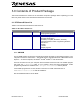
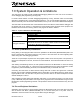
3.0 Contents of Product Package This section describes the contents of the HTS Demo Kit product package. When unpacking your HTS Demo Kit, please check to see that all items listed below are included. 3.1. HTS Demo Kit Item List Table 3-1 lists the items included in the HTS Demo Kit.
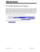
4.0 Limited Guarantee and Support Renesas Technology America, Inc., warrants the HTS Demo Kit to be free from component or assembly defects for a period of 180 days from the date of purchase. Settlement is limited to repair or replacement of the product only. Renesas Technology America, Inc., does not assume any liability arising out of the application or use of any product, circuit or procedure described herein. No other liability or warranty applies, expressed or implied.
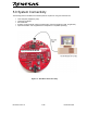
5.0 System Connectivity The following lists the hardware and software products required for using the HTS Demo Kit. • • • • • Host Computer (supplied by user) HTS Demo Kit Board Mini USB cable Software Tools (HEW IDE, NC30 Compiler/Linker, Flash Development Toolkit Programmer) Optional Hardware: User supplied Stereo Headphones or amplified speaker(s). Renesas HTS Demo Board Figure 5-1: HTS Demo Kit Connectivity HTS Demo Kit V1.
5.1. Host Computer Requirements The minimum requirement to be able to use the software that comes with the HTS Demo Kit is a PC with a USB port and Microsoft Windows XP or Vista. 5.2. HTS Demo Kit Board The HTS Demo Kit board provides an evaluation and development environment for the M16C family MCUs. See section “6.0 Hardware” for more details. 5.3. Software Development Tools The installer program installs all the development tools. For details on installation, see the QuickStart Guide.
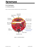
6.0 Hardware 6.1. HTS Demo Kit Board Figure 6-1 shows the HTS Demo Kit Board with major components identified. Renesas HTS Demo Board Figure 6-1: HTS Demo Kit Board HTS Demo Kit V1.
6.2. HTS Demo Kit Board Block Diagram The HTS Demo Kit board incorporates an M30260F8AGP (48-pin QFP) from the M16C/26A group of microcontrollers, designated as U6. Figure 5-2 shows the HTS Demo Kit block diagram. Figure 6-2: HTS Demo Kit Block Diagram 6.3. M16C/26A Group of MCUs The M16C/26A group of 16-bit single-chip Flash microcontrollers (MCU) is part of the M16C/Tiny family and utilizes an M16C/60 series CPU core.
7.0 System Operation & Limitations The HTS Demo Kit board provides sophisticated debugging features at a low cost via its on-board incircuit debugging and programming circuitry (ICD). For M16C boards without on-board debugging/programming circuitry, Renesas offers the functionally equivalent, standalone E8 in-circuit debugger/programmer. You can find detailed information on the E8 and its functionality in the E8 Emulator User’s Manual, which you can view via the HEW Manual Navigator.
7.3. Memory Map The amount and locations of memory used by the kernel on the HTS Demo Kit board’s M16C/26A MCU are shown in Figure 7-1. Figure 7-1: M30260F8AGP Memory Map with the Kernel Program When the High-performance Embedded Workshop is used in ‘Download emulator firmware’ mode, a dialog box is displayed that allows you to place the kernel anywhere in the available user RAM and Flash ROM. Specify an area that is not used by your application software.
7.4. Register Operation Limitations Table 6-2 lists the limitations on register operation. The registers are inhibited from any modification. If register contents are modified in any way, kernel operation cannot be guaranteed.
When RAM Windows or Variable Watch Windows are refreshed, significant target processing time is consumed during which user application code is not executed. Use caution in using refreshing windows, as it affects the real-time behavior of your application code. 7.8. Performing Debug Using Symbols Normally when a new project is created using HEW, debugging symbols are enabled. If you are unable to view the source properly during debug, add the debug option [-g] in HEW before compiling the programs.
8.0 HTS Demo Kit Board Specifications 8.1. Hardware Specifications Table 8-1 lists the specifications of the HTS Demo Kit Board. Table 8-1: HTS Demo Kit Board Specifications Item Specification MCU M30260F8AGP Clocks Main Clock: 5 MHz resonator, PLL, or ring oscillator Sub Clock: 32.
8.5. Operating Environment Table 8-2 lists the environmental conditions for using and storing the HTS Demo Kit board. Store the board in a conductive bag inside the original factory packaging. Table 8-2: Operating and Storage Environments Environmental Condition Ambient Temperature Operating 0 to 55°C (No corrosive gas allowed) Storage −30 to 75°C (No corrosive gas allowed) HTS Demo Kit V1.
Appendix A. Expansion Headers The M30260F8AGP MCU on the HTS Demo Kit target board is housed in a 48-pin QFP package. Pin 1 of the package is identified by the number ‘1’ on the board’s top silkscreen. The MCU_I/O solder pads, located below the “Renesas HTS Demo Board” sticker, provide access to some of the MCU’s pins. You can use MCU_I/O as test points to check MCU signals or, by mounting your own header, to connect your own external circuitry.
Appendix B. Board Schematic & BOM The circuit board schematic and Bill-Of-Materials (BOM) are available as separate PDF documents. They can be viewed via Start > Programs > Renesas > HTS Demo Kit, or by browsing to the folder C:\Program Files\Renesas\Hew\HTS Demo Kit\Docs and opening the files: HTSdemoKit_RevB.pdf HTSdemoKit_BOM_RevB.pdf HTS Demo Kit V1.
HTS Demo Kit V1.
HTS Demo Kit V1.
Appendix C. HTS Demo Kit Printed Circuit Board 3.500 inch Renesas HTS Demo Board Figure E-1: PCB Top View HTS Demo Kit V1.