
Datasheet


Section 2 CPU
Rev.5.00 Nov. 02, 2005 Page 33 of 500
REJ09B0027-0500
2.5 Addressing Modes and Effective Address Calculation
The following describes the H8/300H CPU. In this LSI, the upper eight bits are ignored in the
generated 24-bit address, so the effective address is 16 bits.
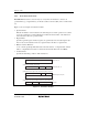
2.5.1 Addressing Modes
The H8/300H CPU supports the eight addressing modes listed in table 2.10. Each instruction uses
a subset of these addressing modes. Addressing modes that can be used differ depending on the
instruction. For details, refer to appendix A.4, Combinations of Instructions and Addressing
Modes.
Arithmetic and logic instructions can use the register direct and immediate modes. Data transfer
instructions can use all addressing modes except program-counter relative and memory indirect.
Bit-manipulation instructions use register direct, register indirect, or the absolute addressing mode
(@aa:8) to specify an operand, and register direct (BSET, BCLR, BNOT, and BTST instructions)
or immediate (3-bit) addressing mode to specify a bit number in the operand.
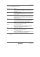
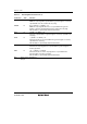
Table 2.10 Addressing Modes
No. Addressing Mode Symbol
1 Register direct Rn
2 Register indirect @ERn
3 Register indirect with displacement @(d:16,ERn)/@(d:24,ERn)
4 Register indirect with post-increment
Register indirect with pre-decrement
@ERn+
@–ERn
5 Absolute address @aa:8/@aa:16/@aa:24
6 Immediate #xx:8/#xx:16/#xx:32
7 Program-counter relative @(d:8,PC)/@(d:16,PC)
8 Memory indirect @@aa:8
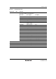
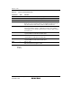
Register DirectRn
The register field of the instruction specifies an 8-, 16-, or 32-bit general register containing the
operand. R0H to R7H and R0L to R7L can be specified as 8-bit registers. R0 to R7 and E0 to E7
can be specified as 16-bit registers. ER0 to ER7 can be specified as 32-bit registers.