
Datasheet

Section 23 Electrical Characteristics
Rev.5.00 Nov. 02, 2005 Page 427 of 500
REJ09B0027-0500
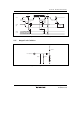
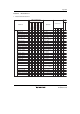
23.3.7 Power-Supply-Voltage Detection Circuit Characteristics (Optional)
Table 23.19 Power-Supply-Voltage Detection Circuit Characteristics
V
SS
= 0.0 V, T
a
= –20 to +75°C, unless otherwise indicated.
Values
Item Symbol
Test
Condition
Min Typ Max Unit
Power-supply falling detection
voltage
Vint (D) LVDSEL = 0 3.3 3.7 — V
Power-supply rising detection
voltage
Vint (U) LVDSEL = 0 — 4.0 4.5 V
Reset detection voltage 1*
1
Vreset1 LVDSEL = 0 — 2.3 2.7 V
Reset detection voltage 2*
2
Vreset2 LVDSEL = 1 3.0 3.6 4.2 V
Lower-limit voltage of LVDR
operation*
3
V
LVDRmin
1.0 — — V
LVD stabilization time t
LVDON
50 — — µs
Current consumption in standby
mode
I
STBY
LVDE = 1,
Vcc = 5.0 V,
When a 32-
kHz crystal
resonator is
not used
— — 350 µA
Notes: 1. This voltage should be used when the falling and rising voltage detection function is
used.
2. Select the low-voltage reset 2 when only the low-voltage detection reset is used.
3. When the power-supply voltage (Vcc) falls below V
LVDRmin
= 1.0 V and then rises, a reset
may not occur. Therefore sufficient evaluation is required.