
Datasheet


Section 20 Power-On Reset and Low-Voltage Detection Circuits (Optional)
Rev.5.00 Nov. 02, 2005 Page 364 of 500
REJ09B0027-0500
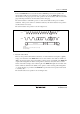
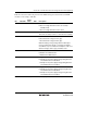
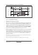
Table 20.1 LVDCR Settings and Select Functions
LVDCR Settings Select Functions
LVDE LVDSEL LVDRE LVDDE LVDUE
Power-On
Reset
LVDR
Low-Voltage-
Detection
Falling
Interrupt
Low-Voltage-
Detection
Rising
Interrupt
0 * * * * O
1 1 1 0 0 O O
1 0 0 1 0 O O
1 0 0 1 1 O O O
1 0 1 1 1 O O O O
Legend: *: means invalid.
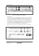
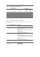
20.2.2 Low-Voltage-Detection Status Register (LVDSR)
LVDSR indicates whether the power-supply voltage falls below or rises above the respective
specified values.
Bit Bit Name
Initial
Value R/W Description
7 to 2 All 1 Reserved
These bits are always read as 1, and cannot be modified.
1 LVDDF 0* R/W LVD Power-Supply Voltage Fall Flag
[Setting condition]
When the power-supply voltage falls below Vint (D) (typ.
= 3.7 V)
[Clearing condition]
Writing 0 to this bit after reading it as 1
0 LVDUF 0* R/W LVD Power-Supply Voltage Rise Flag
[Setting condition]
When the power supply voltage falls below Vint (D) while
the LVDUE bit in LVDCR is set to 1, then rises above Vint
(U) (typ. = 4.0 V) before falling below Vreset1 (typ. = 2.3
V)
[Clearing condition]
Writing 0 to this bit after reading it as 1
Note: * Initialized by LVDR.