
Datasheet


Section 20 Power-On Reset and Low-Voltage Detection Circuits (Optional)
LVI0000A_000020030300 Rev.5.00 Nov. 02, 2005 Page 361 of 500
REJ09B0027-0500
Section 20 Power-On Reset and Low-Voltage Detection
Circuits (Optional)
This LSI can include a power-on reset circuit and low-voltage detection circuit as optional circuits.
The low-voltage detection circuit consists of two circuits: LVDI (interrupt by low voltage detect)
and LVDR (reset by low voltage detect) circuits.
This circuit is used to prevent abnormal operation (runaway execution) from occurring due to the
power supply voltage fall and to recreate the state before the power supply voltage fall when the
power supply voltage rises again.
Even if the power supply voltage falls, the unstable state when the power supply voltage falls
below the guaranteed operating voltage can be removed by entering standby mode when
exceeding the guaranteed operating voltage and during normal operation. Thus, system stability
can be improved. If the power supply voltage falls more, the reset state is automatically entered. If
the power supply voltage rises again, the reset state is held for a specified period, then active mode
is automatically entered.
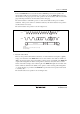
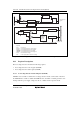
Figure 20.1 is a block diagram of the power-on reset circuit and the low-voltage detection circuit.
20.1 Features
• Power-on reset circuit
Uses an external capacitor to generate an internal reset signal when power is first supplied.
• Low-voltage detection circuit
LVDR: Monitors the power-supply voltage, and generates an internal reset signal when the
voltage falls below a specified value.
LVDI: Monitors the power-supply voltage, and generates an interrupt when the voltage falls
below or rises above respective specified values.
Two pairs of detection levels for reset generation voltage are available: when only the LVDR
circuit is used, or when the LVDI and LVDR circuits are both used.